Unit 3: Grade 10 Technological Design - Robotics - Intro to CAD Drawing Tools
This unit will introduce you to some software drawing tools that can be used in technical design challenges. This will prepare you to work with more complex drawing programs and use these software drawing tools in the design process to support and accelerate virtual design problems.
Course Units and Descriptions
Use this table for an overview and navigate to each of the course unit pages.
| Unit | Description |
|---|---|
| Review course outline for more details | |
| 1 | Careers & Safety- Intro, computers, organization, and careers |
| 2 | Technical Sketching- freehand sketching, ortho, dimensions, ISO views, custom ortho design |
| 3 | Basic 2D & 3D CAD Intro- 2D coordinates, lines, ortho views, 3D drawing, and custom design digitized |
| 4 | 3D Parametric Design- 2D sketch, 3D parts, feature tools, drawings, exporting for 3D printing |
| 5 | Sheet metal Design- thin material design, folds, assemblies, 2D print, project design, testing, and build |
| 6 | Robot Assembly- part reproduction, part assemblies, custom function design and build |
| 7 | Web Portfolio- Showcase course work, projects, and understanding with web portfolio and presentation |
Unit Content Activity Quick Links, Click to Jump to Specific Activity!

- Unit 3, Act. 1: Introduction to 3D Drawing - Google SketchUp
- Unit 3, Act. 2: Introduction to 2D Drawing - AutoCAD Web App
- AutoCAD Web Challenge, Intro, Resources, Tips, Creating ISO,
(Create) AutoDesk Acc/Setup, Step Block, Custom Block, Evaluation - Unit 3, Act. 3: Shaping it on the Cloud - OnShape
- CAD History and OnShape, Intro, Video Sections: 1. Overview and Sketching, 2. Basic Features, 3. Part Design, 4. Assemblies, 5. Collaboration and PDM,
OnShape Online Tutorials: CAD Basics, Fundamentals, Dashboard
(Create) OnShape Reg., Bracket/Gasket, Cylinder/Pitcher, Gripper/Vice, Propeller/Telescope, Headphone/QuadCopter,
Evaluation
 Unit 3, Act. 2: Introduction to Basic 3D Drawing - Google SketchUp
Situation:
Learning to draw and design with different technical drawing programs is a great way to communicate your ideas accurately and can easily be modified to future needs. As a technical design student this can be a very helpful tool with the design process.
Problem/Challenge:

You are to accurately draw the step block we sketched in class and in the previous application AutoCAD Web. Dimensions to be the same as your last project with respect to your career PPT number and to be added in a neat organized manner showing all overall dimensions and detail dimensions. Finished file to be handed in a PDF file format along with a share link.
Investigation/Ideas:

Google SketchUp Introduction
Google Sketchup is a free program and has a lot of support on the Internet including forums, part database, and tutorials. This program is closely used with Google Earth to build and show 3D buildings on it's maps. This program application has many setup configurations to allow different types of drawings and standards. The drawing tools represent simple tools and icons for drawing and push/pull shapes into 3D. This program can be used to draw simple or complex objects very easily. Review your dimension rules and standards and how to keep them to a minimum but also ensure you have enough to re-create it if needed.
Resources
Extra help/resources can be found here if you need more information. Many more resources can be found online showing different methods to draw objects. This is a free program you can download here and installed on your system. The official site will have the latest software which may be different than the version we are using and also includes web-based version . Further resource links can be found here:

- How to Create Your First 3D Model in SketchUp
- How to Use SketchUp
- Sketchup Tutorials for Any Skill Level
- SketchUp tutorials
- SketchUp Help
- SketchUp Tutorial for 3D Printing Beginners
 Official Google SketchUp You Tube channel.
- Learn SketchUp
- Video Tutorials: Getting Started
Create/Construct:
Creating the Step Block using Google SketchUp
Here is a list of the major steps that were show during the class demonstration, and a final 3D drawing sample that you can follow if you need extra support:
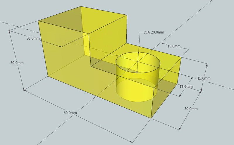
Sample 3D Step Block
- Start SketchUP 2017, select template section: and pick Woodworking Millimeters, for first time using click on the Agree button, otherwise click on the Start using SketchUP button (you may get a message about file locations - just click ok)
- Familiarize yourself with the menu and tool icons, pausing with mouse cursor on icons will give you an idea what that tool icon does, remember to save your work with appropriate file naming convention, and Ctrl S every so often
- Draw a rectangle using the Rectangle tool leaning the right way, then type the x,y (60,30) mm dimensions and press enter
- Use the zoom extents icon to re-size, re-draw and center your object then roll your mouse wheel toward you a bit for some extra working space
- Use the push/pull tool to pull up the object up, type the height Z (15) for additive build method, press enter
- Use the line tool to draw from the mid point snap, then use the push/pull tool pull up the second level of the step block with a height of Z (15) more
- Use the tape measure to to create infinite/construction lines to locate the centre of the bottom step so you can draw your circle 20 diameter, then use the push/pull tool to push down Z (15) to create the hole
- Finish the rest of the block using the same tools/process
- When finished drawing your 3D object, rotate/align the view so that it shows the most features, maximize the landscape orientated space, and allow for adding appropriate dimensions using the dimension tool in the Tools menu
- Show overall and detail dimensions outside of the ISO block envelope following similar techniques and rules with an ortho sketch
- Select the Paint Bucket tool icon then select the Materials panel on the right, then open the Secondary Panel to access and find "Glass and Mirrors" for an approiate translucent colour scheme to compliment the background and contrast the dimensions
- Save in proper file format in two file types: SKP and also export out as a JPG format
- Use File > Export > 2D Graphics for creating the JPG and ensure image/dimensions are fillng up most of the page
- Tip: ensure view is centred and full screen prior to exporting to JPG
When you are finished check with two peers to ensure you have completed the tutorial correctly. When handing in any files, you will submit the in the Drop-Off folder as discussed in class, in the proprietary program file format extension SKP and also export to a JPG format. Ensure the file extension is correct and present. Here are some examples of file name you should be using:
- SKP - Google Sketchup file name example: td2-1_d-joe_2d-step-block_60x30x30.skp
- JPG - Joint Photographic Experts Group file name example: td2-1_d-joe_2d-step-block_60x30x30.jpg
SketchUP in Action, Apply Using the Custom Block Challenge Shapes
Now that you have a some awareness of SketchUp, it's tools, and operation, lets put that new knowledge, skills, and experience to the test using our Ortho note with the block challenge. Select a block challenge object at similar level (see adjacent support table), and build your selected block in 3d, then add dimensions. You are encouraged to collaborate with a partner to discuss things such as the the correct front view of the object, features, dimensions, best ISO view, the acually dimensions in mm, etc. to complete your new 3D ISO block challenge with dimensions.
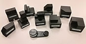
10 Block Challenges
Ortho-Practice
ISO Block Selection:
5A, 5B, (0-60%)
6A, 6B, (60-70%)
7A, 7B, (70-80%)
8A, 8B, (80-90%)
9A, 9B, (90-100%)
Considerations

- Collaboration with partner to discuss which is the correct front view based on the three rules on selecting the front view and the best ISO view to show the most detail and dimensions
- When measuring with ruler, note the edge of the ruler is not always the start of the dimensions, the graduated measuring lines may start a little in from the edge of ruler
- You will need to consider the number of dimension ladders needed around your view - overall and detail, placement, spacing (10 mm, 8 mm there after), grouping, and aligning to look neat and organized and maximize your view space,
- Reviewing dimensioning standards and more collaboration with your partner will help with placement of dimensions
- Visualize basic geometric shapes, using additive and subtrative methods with SkethUp's Push/Pull tool along with the tape measure, and accurate dimensions will allow you to accuratly build your Block Challenge
Evaluation:
The chart below shows you your marks. Remember to save your work with the view you want to first viewed when opened to best show your work that maximizes the space and shows the most features and details of each of your objects.

| Evaluation Breakdown Component Descriptions | Marks |
|---|---|
| Always double check that you have completed all components for full marks. | |
| 3D Step Block Demo - accurate dwg with proper located dimensions (2 files) | 15 |
| 3D Custom Block - accurate dwg with proper located dimensions (2 files) | 20 |
| Total Activity Marks | 35 |
Unit 3, Act. 1: Introduction to 2D Drawing - AutoCAD Web

Situation:
Having now learned about sketching, orthographic and isometric drawings, it is easy for you to communicate effectively with pencil and paper throughout the technology design process. With the advancement of computers and software applications, it has helped people today get things done faster, more efficient, and more organized. It has also saved on the environment in many ways including a lot less paper used. Drawing programs have come a long way in the last 15 years and it is a great way to not only communicate, but also modify and update your ideas very easily.
Problem/Challenge:
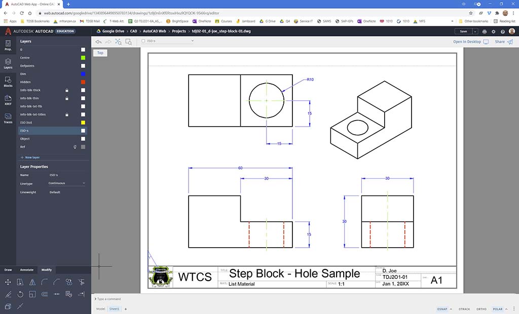
Using the recent orthographic sketch of the step block, redraw it in AutoCAD Web with supplied template. Draw using CAD tools using absolute and relative coordinate system, the three views with additional layers to draw hidden, centre, and dimension lines with suggested colours and weights. Spacing is to be 40 mm between object views. An ISO full scale view is required to draw, to later fit into third quadrant. Finalize by placing your model work in paper space, fill in information block using text tool and submit with a share link and PDF paper space for submitting with self/peer checklist evaluation PDF sheet combined.
Once you have some familiarization with AutoCAD Web, and feedback on your Step Block practice drawing, you are to draw your custom block with the correct front view based on the three rules, dimension with the right amount of dimensions, placement, and space required between views with similar line colouring and weights. Complete your model drawing with proper scaled ISO and then add to your paper space with your information block filled out for share and PDF to submit, including self/peer checklist evaluation PDF sheet combined.
Investigation/Ideas:

AutoCAD Web App Introduction
AutoCAD Web that runs in any web browser has the core power/language and a lot of the tool and functionality of the full desktop version. It has its own cloud storage along with support for some other common cloud services such as One Drive and Google Drive. With core AutoCAD commands available, there is a lot you can do with this web App. It can work with blocks, command line, and icon tools. With the flexibility of working from any web browser, allows you to use light weight computers and mobile access.
This type of program is commonly used in a variety of fields where layout drawing plans are needed to communicate a lot of information graphically. Drawings use the Cartesian coordinate system and there are two major ways to enter lines, either absolute or relative coordinates. Simply put absolute coordinate system uses point entry method based on a single starting point or origin, where the relative point entry method you enter coordinates based on your last coordinate location. With the coordinate system you can enter in such as Cartesian (2D / 3D), polar (2D), cylindrical (3D), spherical (3D) with Cartesian and polar most often used. Before starting to draw your step block, explore the program, experiment with different tools and familiarize yourself with the applications interface, as it is the staple CAD program used in industry. Below are several resource links you can checkout for further details about AutoCAD web.
AutoCAD Web Support links
- AutoDesk AutoCAD Web
- AutoDesk Web App Info
- AutoDesk student account
- AutoDesk license support
- ** AutoDesk Web App Support
- * Hitchhikers Guide
- AutoCAD Web App Review
- AutoCAD 2020
- Intro AutoCAD web App 2.02
- UI Overview, 3.07
- Multi-view guide 34.01
- Seamless Work-flows 57.17
- Intro and samples 7.17
- Ortho construction 17.17
- Basic tools, 13.00
- AutoCAD Top 10 info, 57.17
AutoCAD Web Tips,Tricks, and Key Information

- General settings go to gear icon, top right, to change preferences, tracking, object snap, units, and navigation settings
- Ctrl S to save your work often, so as to not lose any work if a problem occurs
- Command line to enter common CAD typed commands for quick access to tools such as line, grid, units, etc.
- Z for zoom, then letter for type of zoom such as E for extents, A for all objects, etc.
- Absolute coordinates allows you to enter location based on the origin point in relation to where you want to draw or locate a element
- Relative coordinate entry allows you to enter a location based on last location
- When drawing lines, having Ortho Snap on, you can save some time drawing lines that are straight horizontal or vertical by using the cursor to show direction, then just enter in the distance and press enter to draw that line
- The "From" CMD will allow you to offset your starting point location of a line or object
- Osnap (object snap) allows you to quickly lock onto common feature points of lines or shapes depending on which ones you have active
- Otrack (object snap tracking) will allow you to align an edge or e-snap point to another view or drawing location
- Use Layer Manager to create new layers to manage different parts of your drawing like object, text, dimensions, notes, special views, etc and control colour, view, line thickness, line type, layer, scale, locking etc.
- Layer or selection changes you may need to scale dimension lines, arrows, text, special lines, etc, doing so with a selected component will only change what is selected, or with no selection will change everything on that layer
- Draw tab icons: will give you access to drawing different shapes -rectangle, circle, polygon, and also arc, spline, xline, line, polyline, hatching, array, divide, and ellipses
- Annotate tab: gives you access to measure, revcloud, dimension, mtext, mleaders, and vports
- Modify tab: gives you access to move, stretch, mirror, round, chamfer, copy, trim, erase, rotate, scale, offset, join, matchprop, extend, explode, and breakpoint
- Using different object components it is recommended to create/organize them on separate layers, thus giving you more control on your drawing
- Adding new specialized lines, you may need to load them from the library to insert into layers
- Line weights in model space may not show up in the same scale as your paper space, so you may need to adjust your scaling in your model space so that it shows properly in paper space
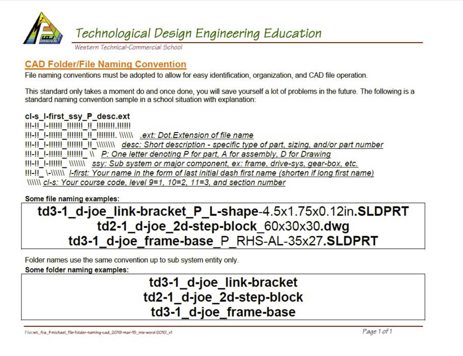
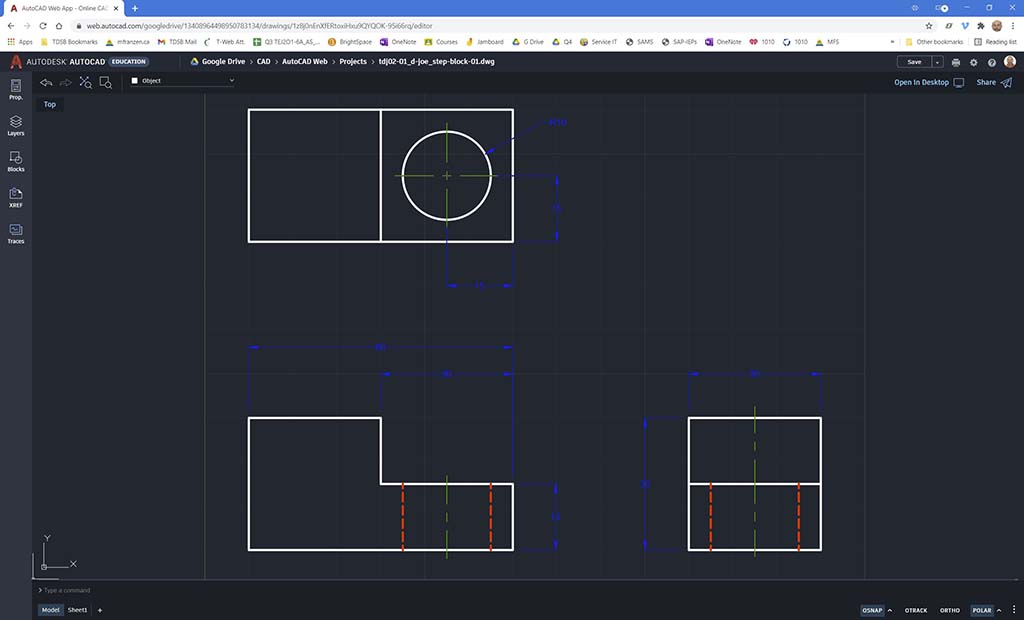
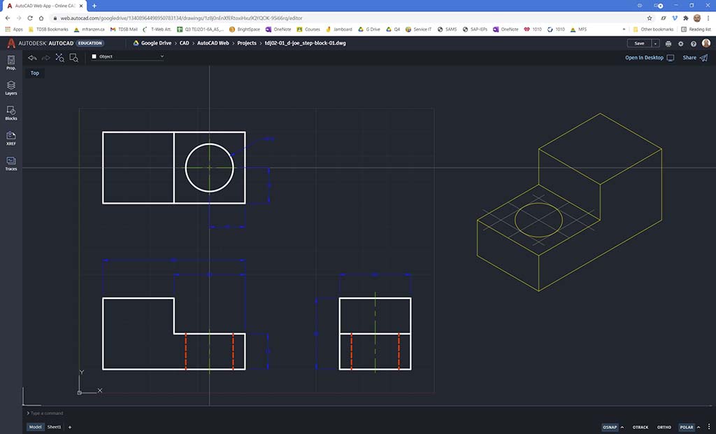
AutoCAD Web ISO Drawing View
- Adjust POLAR to 30° for making your isometric, this will create the angles you need to build your object in ISO
- For non-cylindrical objects use the line tool create your ISO on a new layer (ISO-scaled), start a line off the right side of your drawing views full 1:1 scale by moving the mouse in the direction you want catching those 30°POLAR angle snaps.
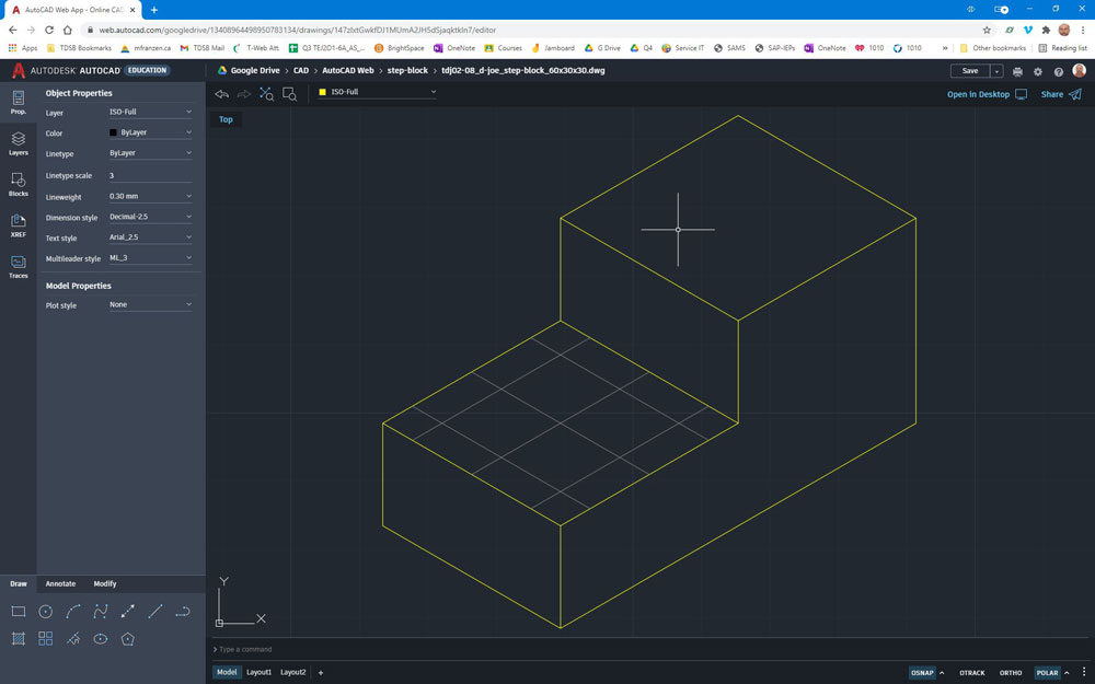
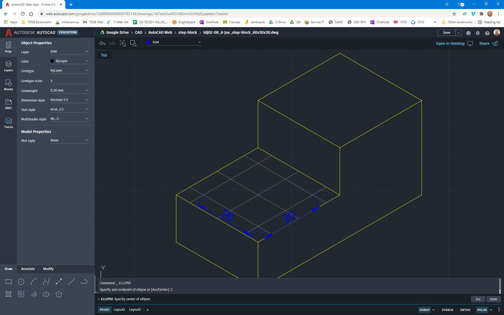
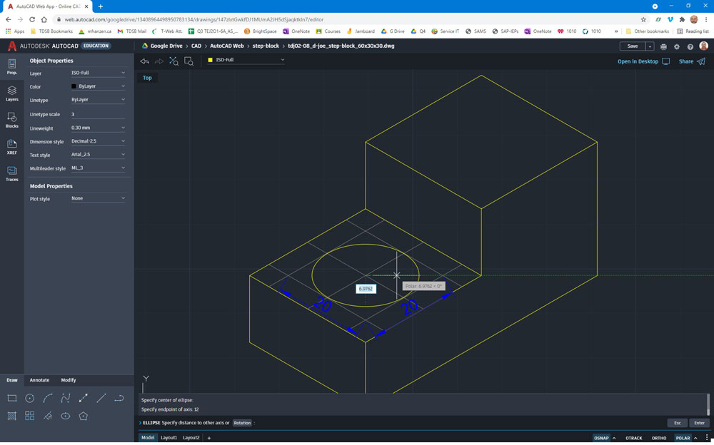
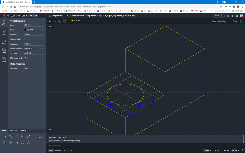
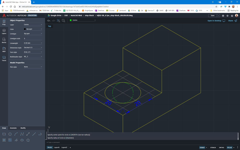
- For ISO circles, a regular circle will not work and there is no specific tool in AutoCAD Web, so we will create something close by use of the ellipse tool and some centre and grid references lines to draw a similar ISO circular hole on the ISO plane (see images below for visual of steps 4-6)
- Create reference ISO centre lines for your circle (continue using polar 30°), then use the copy tool to create parallel lines using your circle radius from centre out, to, form an ISO box, the diameter of your circle
- Using centre ellipse tool, with centre option clicked on command line, select the centre of your ISO box, move your mouse in the direction of one of two furthest end ISO box intersections to a distance of your circle radius+20% or {(R*.2)+R}, turn off any OSNAP's, tracking, and POLAR, then adjust your elliptical to fit your ISO box, to create a very close to correct leaning ISO circle - note sample in picture below is for a 20 mm circlie with R=10, therefore use 12 or {(10*0.2)+10} for the initial ellipse radius
- Once finished your ISO, make a copy of your ISO, move to your object view layer, then use the Scale command (with appropriate scale ratio) to reduce your copy to fit appropriately in the third quadrant of your orthographic drawing, and hide/freeze your original ISO and reference line layer
ISO Grid
Ellipse
Radius
Adjust
Difference
![]() With the current version of AutoCAD Web there may be a possible bug when you try to change the name of, or create/add another sheet on the bottom tab, that it pushes the whole body up, to the point you don't have access to the CAD workspace, command line, and tools.
With the current version of AutoCAD Web there may be a possible bug when you try to change the name of, or create/add another sheet on the bottom tab, that it pushes the whole body up, to the point you don't have access to the CAD workspace, command line, and tools.
Create/Construct:

Creating an AutoDesk Account to Use the AutoCAD Web and Set-up
To use this free AutoCAD Web App, you will first need to create an account with AutoDesk, the developers of AutoCAD Web.
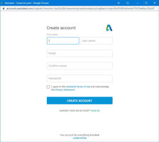
- Go to the AutoCAD Web App sign-in page, and click below the Create free account where it says student or educator, to create a student education account
- Click on the "How it works" (3:08 min.) to see the process, the click on the black "Getting started" button to start the registration process
- Fill in your info including your first and last name, your school email, and a secure password, note you may already have an account through TinkerCAD or similar application, which you will just need to link to your school email and update your educational status for the free access (similar process below)
- Check agreement statement for terms of use and click on Create Account
- You will need to confirm your email address when you get an email from them to finalize your registration, click on Getting Started button for AutoCAD Web, fill out one final form for your status, and provide proof of being a student - a picture of your student card should be sufficient or other preferred documentation
- Congratulations, you should be ready to start using AutoCAD Web App by now signing-in
- You will want to connect your school Google Drive account, by using the Add storage provider box, and selecting the Google Drive icon and adding your school Google drive. Once confirmed, AutoCAD Web will be able to save and open files in your Google Drive with seamless integration
- In your Google Drive folder for this class, create sub-folders; tdj > cad > autocad-web, then create a sub-folders for each projects you will work on, so you keep your files and projects organized, just like you did with your local USB drive main save location, that you created earlier in the course
- Get the following template files (template file and image logo), which has a completed paper space title block done for you with some global settings updated, and copy downloaded template files to a sub-folder; tdj > cad > autocad-web >templates, so you can reuse this for each of your projects
- Create another sub-folder; tdj > cad > autocad-web >your "project" name (Step Block demo) so you have a place to save your first 2D AutoCAD Web App project
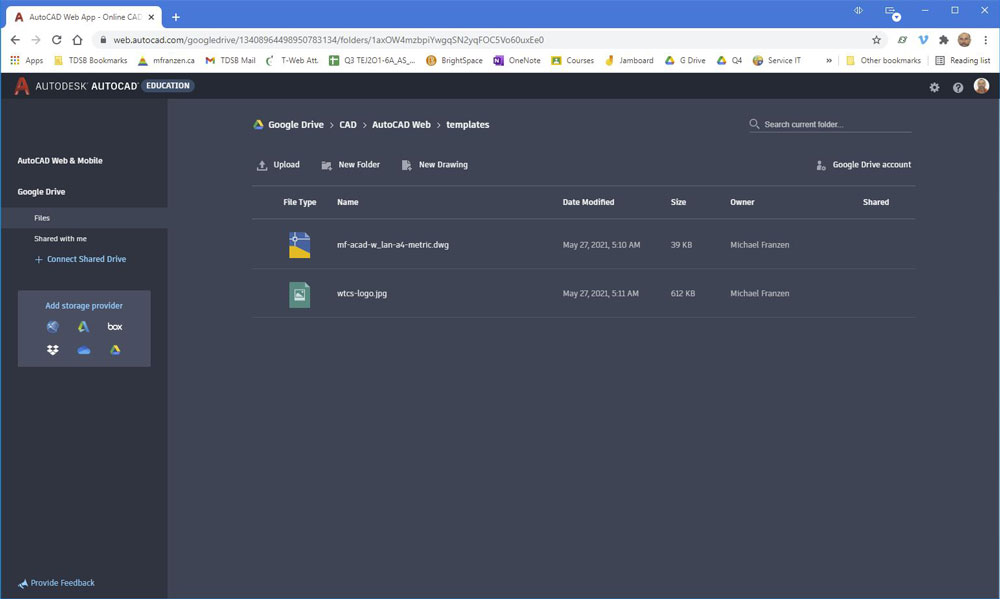
- For marks, submit a JPG screen capture of your AutoCAD Web workspace, showing your Google drive opened up to; tdj > cad > autocad-web >templates, with the new template in clear view (sample shown)
Educational Registration
Set-up
![]() You should already be using Chrome, but just in case, support states that the AutoCAD Web App is supported also with Mozilla Firefox, and Microsoft Edge, you can check out the more details and features here on AutoDesk knowledge network.
You should already be using Chrome, but just in case, support states that the AutoCAD Web App is supported also with Mozilla Firefox, and Microsoft Edge, you can check out the more details and features here on AutoDesk knowledge network.
Creating Step Block (as a practice sample) in AutoCAD Web
Using the AutoCAD Web App, create an orthographic drawing of the "step block" (i.e. create your selected block design file) with separate layers for reference, object, hidden, centre, dimension, ISO full, ISO scaled layers in model space and then printing the paper space output to PDF, using the steps below and include your ![]() 2D CAD Ortho Self-Peer Checklist.:
2D CAD Ortho Self-Peer Checklist.:
Picture Samples of Demo
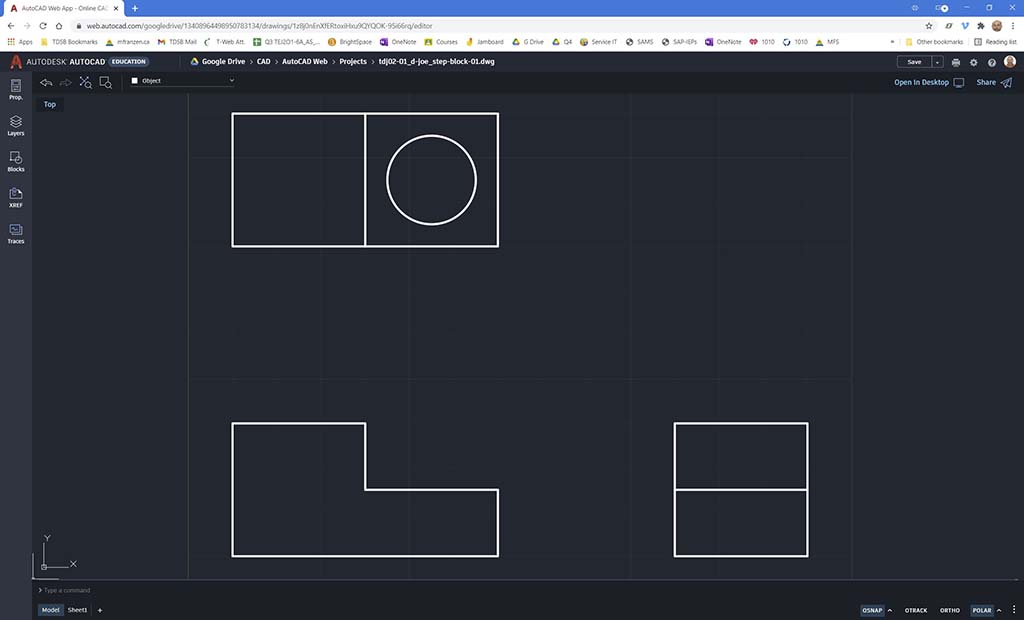
Object Views
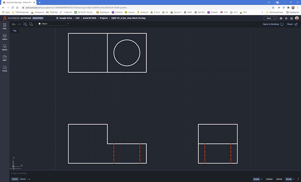
Hidden lines
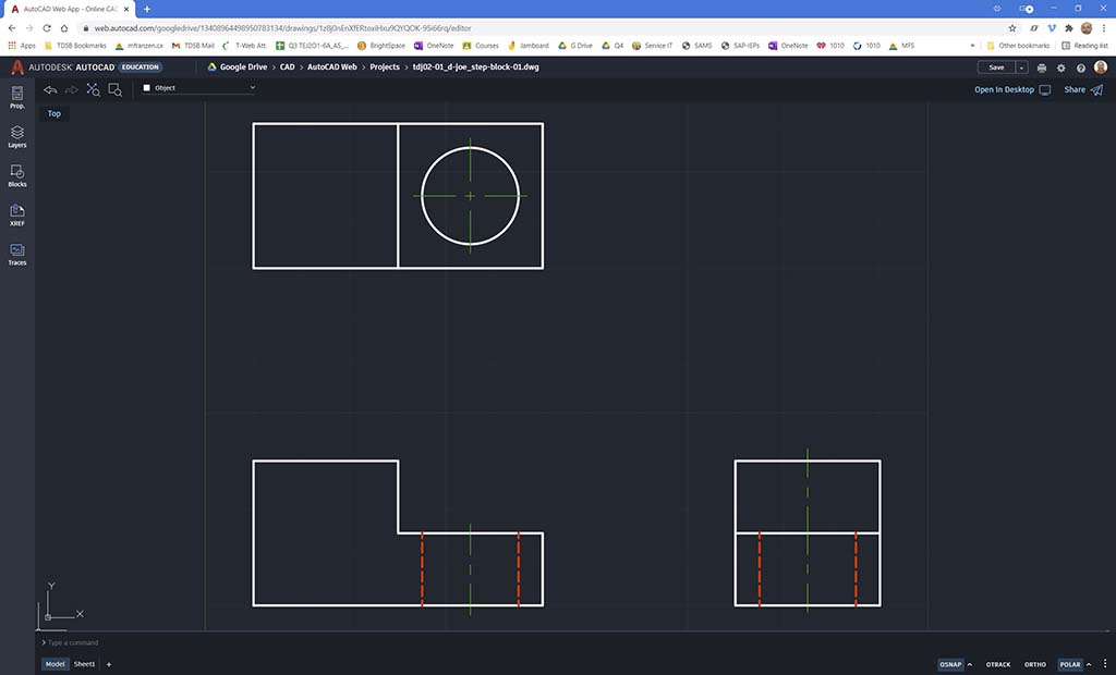
Centre Lines
Dimensions
- Create a new file from mf-acad-w_lan-a4-metric, select the template file you recently acquired
- Running AutoCAD Web for the first time you may want to change some of the settings such as in preferences, the dark or light theme as an example
- Type "z" for zoom, then "e" for extents, to show the whole model workspace
- Create an new layer and name it Object (for object lines), set it as white and make it a continuous line type, FYI - Layer 0 is usually reserved for making blocks (customized smaller CAD shapes to be re-used)
- Using your career PPT number = C, you will customize your Step Block dimensions length 50+C, Width 20+C, Height 20+C, and hole Diameter 10+C, so that everyone will be making the same object, but custom sizing
- Use the polyline tool to create the outline of your object by entering in the command box the absolute coordinates "10,10" ((X,Y)) as your starting point (to space away from bottom left corner) and then use relative Coordinates "@50,0" (click on command line entry text) to create a line from current position (10,10), 50 units long on the X axis with no distance on the Y axis -i.e. a straight line to the right, then continue with the next 4 polyline segments of the object polyline segments,(next command would be @0,10 and the next would be @-20,0 and so on) to finish the front view, and for the last polyline segment you can just use the shortcut key "c" to close your object shape
- Calculate the 2nd views' absolute coordinate start point, for the right side view (X= 10+50+40= 100, Y= 10, so "100,10", but remember to include your C custom PPT value for your own length 50+C, so the view spacing is correct) and keep in mind 40 units (mm in this case) spacing between object views to start another polyline, and then try relative polar coordinate entry (instead of relative coordinates) by entering "@20<0", with the "@" symbol means relative from current position, then the length of travel units, then the angle "<" bracket representing the angle direction you want to travel, usually 0, 90, 180, 270 degrees, ex. the next command would be @20<90 (this will create a line from current position 20 units long at an angle of 90 degrees, i.e. straight up
- For the top view, again calculate absolute coordinate to start, keeping in mind equal view spacing and try out dynamic entry input method by using your mouse, moving it in the approximate direction you want, then type in the unit distance, then TAB to put the exact angle and press Enter to execute command
- Try the "From" command allows you to locate and create a reference starting point a set distance/angle away, such as the one of the internal object feature lines, using the line tool. You can also experiment with the OSNAP (Object Snap)
 Use the Paper Space sample below, to compare what to complete
 - The circle/hole can be created using the circle tool and locating it in several ways such as using the From command to locate the centre of the lower step, or you could use a diagonal line since it is a square, then use the OSNAP mid point to locate your circle, or you could just calculate the absolute coordinates for the centre of the circle to place it
- Using the layer commands, make a new layers for hidden lines, centre lines, dimensions, ISO original, and ISO scaled, with each of their properties for object line weights of 0.60, hidden line weights 0.50, dimension and centre lines at 0.30 weight, using colours in sample shown
- Now you can select appropriate layer such as hidden and centre lines, and then locate and draw them in, so they are individually controlled on their independent layers, then you can also insert the dimensions also on the dimension layer (see examples pictures above/below)
- In the Object Properties icon & Panel, you can adjust the line types and set scales for each of your object entities to override your global settings "Bylayer", so for each hidden line, change the line scale to 6 and each of the center lines, change scale to 10 (so they print/plot properly, later on), and before you add your dimensions also update your Dimension Style in the Object Properties to Decimal-2.5 and then put the rest of your dimension in
- For the isometric, creat/set your ISO -Orig layer, set your POLAR button (at the bottom right) to 30° and turn on, so that you can use a dynamic Relative Polar Coordinate cursor direction and distance and draw the isometric of your object , at full 1:1 scale, outside your ortho drawing limits/envelope area, to the right on a new layer- "ISO orig". You will need to draw an "ISO circle" by creating a scaled elliptical for it to look correct. When done your ISO Step Block you will need to copy to a new layer (using copy tool and layer change in properties panel) - "ISO scaled" and scale to fit in your drawing envelope, in the third quadrant
- In sheet view (also known as paper space), you will have to adjust to fit in view port (double click in view port window to activate), then double click on the outside of view port- the paper edge, to complete information block with name, date, material, and class
- Outside of the drawing envelope of all three ortho views with new text entities (new Note Layer), label using the mTEXT tool - Standard, BankGothic, #2 size, the names of coordinate entries types that were used and a sample command entry you used to create that shape, lastly under your Scaled ISO, label "SCALE:" and the actual numbered ratio scale you used to reduce the size from the original size, example 1:0.6
- Make a tall note (add to Note Layer) on the right side of page, beside your ISO down to your Side view about 10 units over and about 40 units wide, using the mTEXT tool - Standard, BankGothic, #1.5 size, bylayer, to number and list the first 15 of your steps you took (~2-4 words each) using key terminology in simple short points, with title "Key Steps", when done, highlight the title and change size to #2 and select bold,
- In paper space you may want to turn off the grid, if it is interfering with your view in the title block body, fill in the information block with title Step Block 60x30x30 (use your customized size), your last intial, first name, course code, date, Dwg #A1, scale 1:1 and material "PLA- polyactic acid"
- Review/double check the steps above to ensure you have completed all work and it is done correctly, then "PLOT" (print) your paper space CAD file as a PDF (double check hidden and centre line scales, adjust in model space if necessary), screen capture to JPG your zoom extents of your model space screen showing all of your work with layers panel shown on left and convert to a PDF, then combine both with your Model Space image for your first page and plot to print of your paper space print ortho layout for your second page, to pass on to your peer evaluator
- Peer evaluator to look at the combined 2 page (CAD model and sheet drawing) to review partners work objectively, by putting red coloured critical feedback with peer marker's last initial, first name on both pages at the top and then save the PDF to return to owner to review peer evaluator's red text feedback, update/fix work if needed, otherwise submit your peer reviewed combined PDF as first attachment, upload/attach your your 2nd attachment of your locally downloaded .dwg file, from your G-drive
Starting New Project in "Model Space"
Shape Creation: Different Ways to Accurately Draw lines
Layers and Line Types
Building the Isometric
The Drawing (Paper Space) and Notes/Labels
Self/Peer Eval
Picture Samples of Demo
ISO Full Build
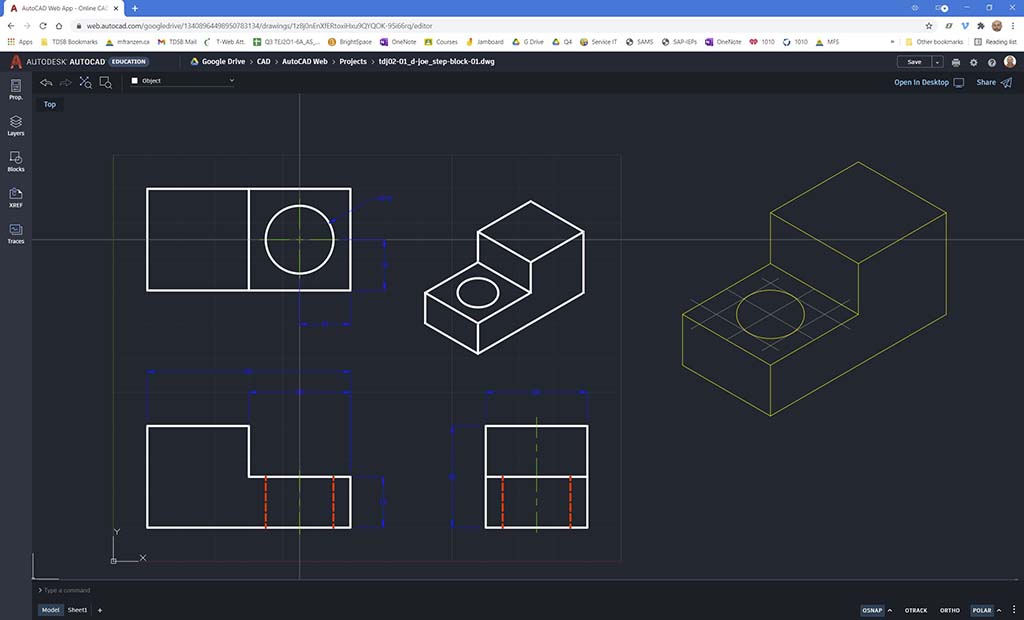
ISO Reduced
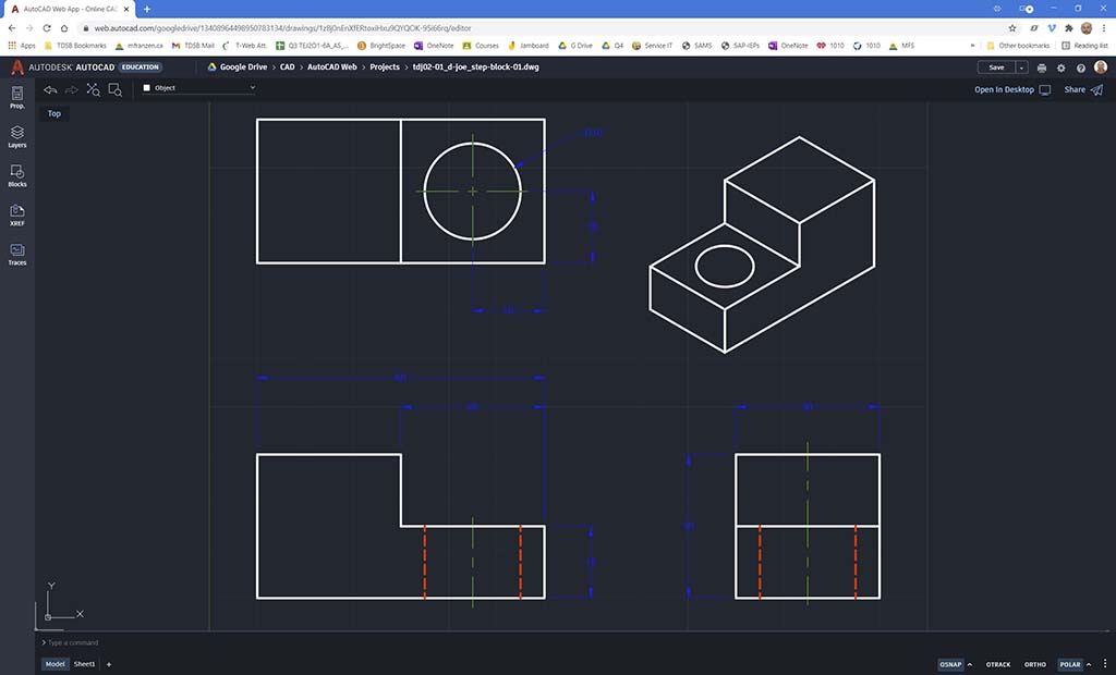
ISO Move
Paper Space
![]() Ensure the file extensions are correct and present. Ensure you have your PDF combinded file looked over by a peer mentor with their feedback on the top of each page. Here are examples of file naming conventions you should be using for CAD files:
Ensure the file extensions are correct and present. Ensure you have your PDF combinded file looked over by a peer mentor with their feedback on the top of each page. Here are examples of file naming conventions you should be using for CAD files:
- AutoCAD Web proprietary file format DWG: tdj2o1-1_d-joe_2d-ortho-iso-step-block_60x30x30.dwg
- PDF: tdj2o1-1_d-joe_2d-ortho-iso-step-block_60x30x30.pdf
AutoCAD Web in Action Using the Custom Block Challenge
10 Block Challenges
Ortho-Practice
Now that you have some experience with AutoCAD Web, it's tools, and operation, lets put that new knowledge, skills, and experience to work and use your previous block challenge. Using your block, you did with SketchUp and its dimensions, create your new model drawing for that block. You are encouraged to collaborate with your partner to discuss things such as the correct front view of the object, features, dimensions, best ISO view, CAD tools, etc. to complete your new ortho/ISO block challenge with dimensions. No side note will be necessary this time, just focus on your ortho, ISO views in model space and then fit in paper space with information block filled out, and use the ![]() 2D CAD Ortho Self-Peer Checklist to complete for feedback and possibly improve your work/mark.
2D CAD Ortho Self-Peer Checklist to complete for feedback and possibly improve your work/mark.
Considerations
- Collaboration with partner to discuss which is the correct front view based on the three rules on selecting the front view
- As this project is similar to the step block in terms of layers, you may use your step block file with the Save As command, and then delete your model object views, to re-use the layers
- You will need to consider the number of dimension ladders needed between views (40 mm will work with three ladders or levels like in the step block... it will depend on the amount of details your object new object has) and you want about 10 mm spacing around the views and the boarder, i.e. use your paper space effectively
- Reviewing dimensioning standards and more collaboration with your partner will help with placement of dimensions
- Remember to create your ISO view last, once you know how much space you have with dimensions placed, then creating your ISO at full scale, copying it, and then reduce to an appropriate scale that will fit in the third quadrant of your model space drawing
Evaluation:
Ensure that you have followed instructions and completed all steps taking in account the object layout, set-up, location, and final drawing output files. Ensure you have your CAD file and ![]() 2D CAD Ortho Self-Peer Checklist completed and combined with proper file naming convention for submission.
2D CAD Ortho Self-Peer Checklist completed and combined with proper file naming convention for submission.

| Evaluation Breakdown Component Descriptions | Marks |
|---|---|
| Always double check that you have completed all components for full marks. | |
| ACAD Set-up - Account set, folders organization, and template file | 10 |
| ACAD Step Block - follow tutorial/example, model, DWG, and eval. sheet, share link | 35 |
| ACAD Custom Block - Rough notes/calculations, model, DWG, and eval. sheet | 40 |
Unit 3, Act. 3: Shaping it on the Cloud - OnShape
Situation:
Students are exploring different CAD related programs to get a feel for related tools used to design and draw.
Problem/Challenge:

Students will familiarize themselves with the history of CAD then go through a number of tutorials introducing the basics of 3D CAD using OnShape. The tutorial sections to complete are:
- Overview and Sketching
- Basic Features
- Part Design
- Assemblies
- Collaboration and PDM
Students will view the tutorial videos of each section, then follow the project step instructions to complete the 2 related tasks and later try the practice quiz's to test their knowledge and understanding of the work completed.
Investigation/Ideas:

CAD History and OnShape

Looking a little closer at the history of CAD can give you a better context of where CAD is today and its future. This will also give students a better understanding of OnShape in comparisons to traditional CAD programs that commonly run locally on your computer.
- History of CAD, 4.15
- OnShape - About Us
-
 OnShape General
 - OnShape Help Documentation
 History of CAD, 92s
 General Intro to CAD, 17s
- What is CAD-CAM, 12s
- What is Onshape?, 2.14
1. Overview and General Resources
This section introduces you to 3D modeling, OnShapes' interface, design intent, sketching basics,dimensioning, and constraints. Getting Started video is a great start to start working with OnShape. After being introduced to OnShape, you will have complete some tutorial videos, and start on a related drawing project to model and draw, practicing methods, experience CAD tools, and learn some new techniques with sketches, dimensioning, and constraints. Here is a ![]() set of 10 introductory videos that go into detail with some of the basics of OnShape.
set of 10 introductory videos that go into detail with some of the basics of OnShape.
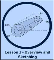
1. Overview and Sketching
This section introduces you to the program, user interface, design intent, and getting started with using OnShape.
Tutorials
- Software Overview and User Interface Tour, 4.56
- Parametric Modeling and Feature-Based Modeling, 6.01
- Design Intent, 4.44
- Sketching Basics, 3.56
- Dimensions and Constraints, 4.25
- Extrude Feature Tool, 3.25
- Make a Part - 3D Feature, 4.48, Mobile, 4.52
- Make a Part - Drawing, 2.53
- Drawing Essentials, 5.04
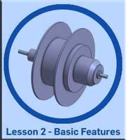
2. Basic Features
This section introduces you to several feature tools: extrude, revolve, sweep, fillet, chamfer, shell, and draft. Direct editing allows you to modify, delete, replace for example using the Move Face tool for translating, rotating, or offsetting components of your object.
Tutorials
- Revolve Feature Tool, 1.56
- Fillet and Chamfer Feature Tools, 2.59
- Sweep Feature Tool, 2.27
- Draft and Shell Feature Tools, 2.38
- Direct Editing Feature Tools, 3.55
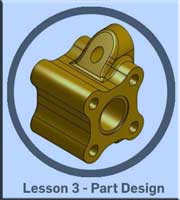
3. Part Design
This section introduces you to starting a design, showing a part design example, looking at a machine part design case study, a multi part design, plastic design, consumer product case study and a medical device case study
Tutorials
- Starting a Design, 6.10
- Part Design Example, 10.28
- Machine Part Design Case Study, 6.10
- Multi-part Design, 3.14
- Consumer Product Case Study, 8.34
- Medical Device Case Study, 8.51
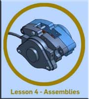
4. Assemblies
This section introduces you to assemblies, sub assemblies, single documents, assembly mates, and an assembly design case study.
Tutorials
- Introduction to Assemblies and Sub-assemblies, 7.13
- Single Document, 6.11
- Assembly Mates, 6.43
- Assembly Design Case Study (Brake Caliper), 13.51
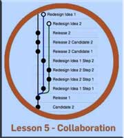
5. Collaboration and PDM
This short section introduces you editing history, versioning, collaboration with simultaneous/branch editing, and working with existing CAD files.
Tutorials
- Edit History and Versioning, 3.00
- Collaboration (Simultaneous Editing and Branch Editing), 6.28
- Working with Existing CAD Files, 4.25
Once you have setup an account from the OnShape browser web App, you can use the Learning Centre button, top right to access a ton of resources. EDU Onshape subscriptions receive access to all of the self-paced content, technical briefings, and videos in the Learning Center for free. The learning pathways are great a great place to start, learning about OnShape, and the Dashboard keeps track of what you have reviewed. More about the Dashboard below.
![]() For your convenience, if you are already logged into your OnShape account, then the links below will allow you access to the courses below, so just remember to log-in first to OnShape, otherwise you will hit a firewall account block.
For your convenience, if you are already logged into your OnShape account, then the links below will allow you access to the courses below, so just remember to log-in first to OnShape, otherwise you will hit a firewall account block.
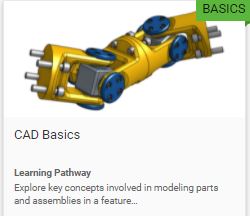
OnShape CAD Basics
Under the Learning Pathways, Select OnShape CAD Basics and get started with the following self-paced tutorials with the links taking you to the first the course tutorials in each of the areas below:
- Introduction to Parametric Feature-Based CAD
- Introduction to Part Design
- Introduction to 2D Drawings
- Introduction to Assembly Design
OnShape Fundamentals: CAD
Under the Learning Pathways, Select OnShape Fundamentals:CAD and get started with the following self-paced tutorials with the links taking you to the first the course tutorials in each of the areas below:
- Navigating OnShape
- Introduction to Sketching
- Detailed Drawings
- Part Design Using Part Studios
- Multi-Part Part Studios
- OnShape Assemblies
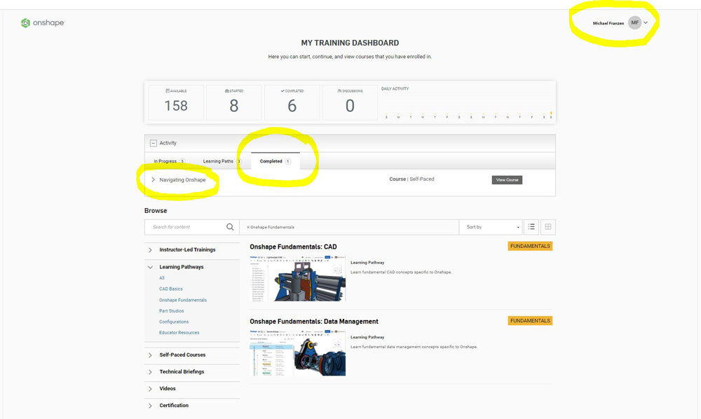
Your Learning Dashboard
Your Training Dashboard keeps track of what you have accomplished so you can start, stop, continue with each of the online courses you have enrolled in. You may be asked to take a screen shot of completed course tutorials to show what you have completed. A sample screen shot of the Navigating OnShape is to the right, note before taking a screen shot, use the zoom to have your name and completed course shown.
If you wish to go further on your own, at your own pace and interests, OnShape has several other courses to further broaden your learning with OnShape.
Create/Construct:

OnShape Registration

Before you can start using OnShape, you will need to register for a student EDU account - ![]() video process.
video process.
- upload a recent face image of yourself,
- put your nickname as last initial, first name example D, Joe
- fill in your general information,
- default settings such as units length = mm, angle= Degree, and mass= Kg
- leave mouse settings as default
- link your Google Drive
If you want, you can complete tutorials that introduce the fundamentals of OnShape navigation, sketching, drawings, parts, and assemblies. Review CAD drawing tools, methods, and techniques in OnShape that you will find similar in other common CAD programs.

You should be using Google Chrome (or Firefox Mozilla) to work with the OnShape CAD engine on the PC, so ensure that you set your default browser so that when you click on a web link from your computer that it goes to Google Chrome and not Explorer. If not set, you will need to copy the link manually into memory, and paste into Google Chrome browser. You may need to test and/or adjust some settings on your recommended browser.
1. Overview and Sketching Projects
This section introduces you to 3D modeling, OnShapes' interface, design intent, sketching basics,dimensioning, and constraints. After you have reviewed the tutorial videos, you will be given two related drawing projects assignments to draw, follow methods, experience CAD tools, and learn some new techniques with sketches, dimensioning, and constraints. Ensure you have reviewed the related video's in the Investigation section above before starting drawing projects below.
Drawing Project Instructions
When you follow the PDF instruction sets, you will be given a link to a OnShape template which you will need to log-on to site first. Set-up your Google Chrome Browser and opened PDF instructions for quick application switching such that you can ALT+TAB between them or if your PDF instructions opens with-in a TAB in your browser, then use the ALT+CTRL to toggle between each. You will need to make a copy of the template (create a new file based on original and name new file name).
Remember to save the file with the proper file naming convention: course code two letters and level, course section, project name, your last initial, first name, and description format. Example: tdj2o1-01_d-joe_2d-step-block_60x30x30
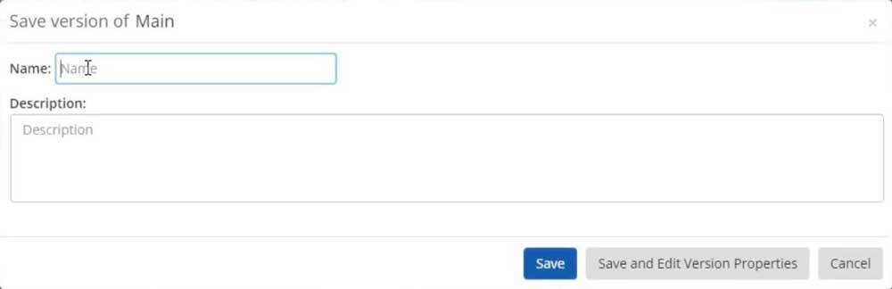
After final save, also do a version save!
Once finished the assignment, you will need to create a final version "FV1" using the manage version button, use the description area to add supporting notes, then save version, and share it with your instructor (use e-mail address from the bottom of this page) so your instructor can view with full edit access for evaluation. Ensure you include your evaluation self/peer checklist sheet with your submission.
 Make sure you have all your sketches Fully Defined prior to extruding, by making sure no blue lines are showing in your sketch (should be all black). Red represents over defined which means there are too many constraints or dimensions and you will have to remove some. Use dimensioning techniques and keep 2D sketch dimension layouts neat and organized. If you find that your part is not filling up with a light grey once you have closed all shapes, then you will need to check your line connections. Also ensure that your version FV1 of your part is showing the best isometric view, fitting on screen.
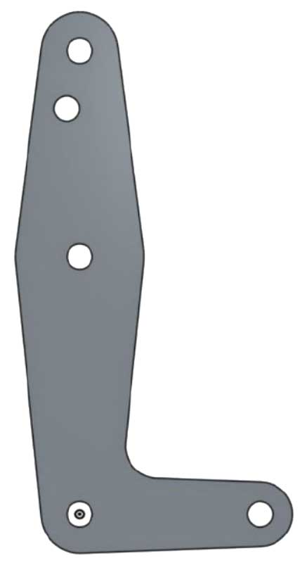
Link Bracket Model
 Basic Sketching - Link Bracket (Also in addition to instruction guide see below):
- Rename with proper file name convention, ex: tdjo2-01-01_d-joe_ link-bracket_P_L-shape-4.5x1.75x0.12in
- Select and draw the correct front view (hint - not the one shown) and keep in mind that your 2D sketch dimensions are required to be organized and fully defined
- Change your tab title to the actual part name "Link Bracket",
- Rename your feature extrude and part name in the feature tree area "Link Bracket"
- Select your part in the feature tree and apply PLA material and pick an appearance colour
Link Bracket Drawing
- Create a standard 3 view ortho with dimensions and ISO using tdj201_mr-f_OS_ANSI_templates file (make a copy for yourself) with template mf-ANSI_A_INCH.dwt set-up to maximize space, then add a drawing using the "+" Insert New Element near bottom tabs, and add drawing using the template you just copied
- Name bottom drawing tab: Link Bracket (note you will have to delete some random empty text fields around the info block area as a result of template update)
- Drawing info block: You need to fill in the properties section of the part or sheet being used. For Material: PLA, Finish: Normal, Weight: (find by selecting your part in your model view, click on small scale lower left corner, copy the weight and use note tool in the drawing tab to insert into info block), Title (input in model properties under Title one), Part & revision Number (input in DWG properties), Checker and date, etc. (use note tool) 6 mm (0.2362 inches) for title, 3 mm (0.1181 inches) to finish off info block
- Save your version titled FV1, put in the description section: the volume of the part, and five key things you learned in this project (bullets) using correct related terminology
- In the main menu, under Document Properties, put a quick one sentence overview of this project.
- For peer evaluation, save a screen captures of your Link Bracket model sketch showing dimensions, your 3D model ISO, and your drawing into a combined PDF with you self/peer OnShape Model/DWG Checklist evaluation sheet last, for your peer reviewer to put their name and annotate critical support comments, and fill in the marks for the peer evaluation when you get back fix if necessary and add on top screen caps of those fixed pages if necessary
- Submit your combined PDF Model sketch with dimensions, 3D model, drawing, and your S/P Eval sheet AND click on Share button to share with teacher (email address) with full edit access - with "Can Edit" your digital file (correctly named, ex: td2-1_d-joe_link-bracket_P_4.5x1.75) with instructors email address (found bottom of all web pages here) for evaluation and feedback
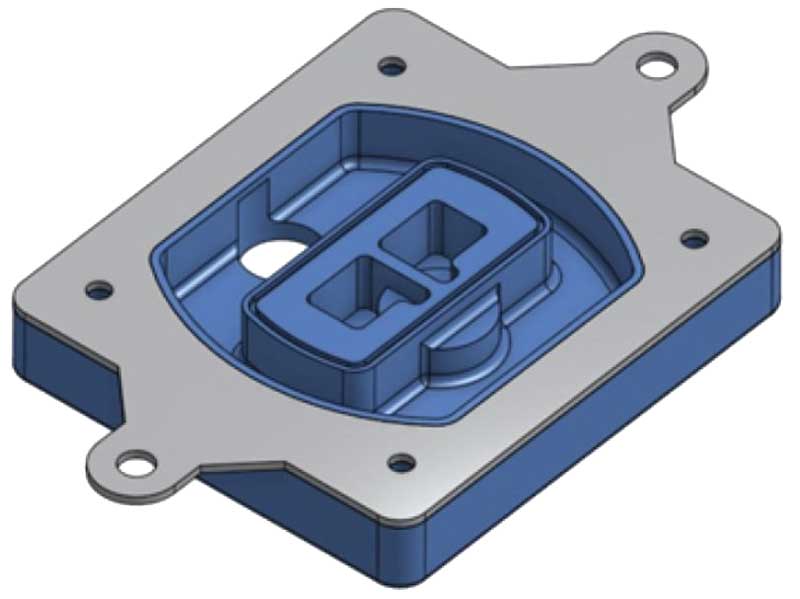
Mouuld Gasket
- Sketching In-Context - Mould Gasket Also in addition to instruction guide:
- Ensure the last step of the instructions, that the length change update is affecting the same direction as the gasket holes you just added,
- Create a description of the whole project (hint use PDF goals to summarize) for the whole project file using Main Menu (three thick horizontal bars)-Document Properties
- Assign a material to silicon rubber for the gasket,
- Edit part appearance colour to # b6c2cc (grey) by left clicking on your part in the feature tree panel area,
- Change your tab title to the actual part name "Mould Gasket",
- Rename your feature extrude and part name in the feature tree area "rubber gasket",
- Save a final version FV1, put in the description the Mass in kg, volume in mm3, and Surface area in mm2 of the part, and number/list five key things you learned in this project using the correct terminology
- Use the OnShape model checklist sheet to ensure you have completed the project correctly and remember to peer mark only once to ensure everyone gets that opportunity and not lose marks
2. Basic Features
This section introduces you to several feature tools: extrude, revolve, sweep, fillet, chamfer, shell, and draft. Direct editing allows yo to modify, delete, replace for example using the Move Face tool for translating, rotating, or offsetting components of your object. Ensure you have reviewed the related video's in the Investigation section above before starting drawing projects below.
Drawing Project Instructions
Follow the instructions in the PDF's below to complete your drawing projects, remember log-on, proper file naming convention, and finish with final submission version fv1, and sharing for evaluation.
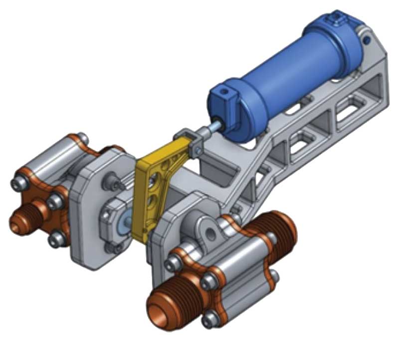
- Basic Features 1 - Cylinder Note step 3, ensure you select the whole triangular profile, minus the hole, to successfully "add" extrude to part. Also in addition to the instruction guide:
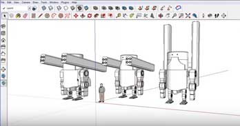
Hydraulic Cylinder OnShape Model
- Change your tab title to the actual part name "Hydraulic Cylinder",
- Create a description of the whole project (hint use PDF goals to summarize) for the whole project file using Main Menu (three thick horizontal bars)-Document Properties
- Rename your feature extrude names in the feature tree area as you add more features such as; cylinder, Base left triangle, Base right, Base right vert hole, and Base left vert hole,
- Assign a material to the part: aluminum 7075,
- Edit part appearance colour to # 5387C0 (Blue) by left clicking on your part in the feature tree panel area
- Left extrude, ensure you select hidden rectangle, right click, select other
- You can save particular views, click on view icon, select Named Views, and save current view (hint if you need a particular view not normally able to select when bringing into drawings later)
- Cylinder features added i.e. extrudes are all of the same part, so do not make new parts when adding features or you will not be able to apply the fillet tool later
Tips
- Create a standard 3 view ortho (correct front view placed) with dimensions and ISO using template mf-ANSI_A_INCH.dwt set-up to maximize space
- Name bottom drawing tab: Cylinder (note you will have to delete some random empty text fields around the info block area as a result of template update)
- Drawing info block: You need to fill in the properties section of the part or sheet being used. For Material: ALU 7075, Finish: Brushed, Weight: (find by selecting your part in your model view, click on small scale lower left corner, copy the weight and use note tool in the drawing tab to insert into info block), Title (input in model properties under Title one), Part & revision Number (input in deg properties), Checker and date, etc. (use note tool) 6 mm (0.2362 inches) for title, 3 mm (0.1181 inches) to finish off info block
- Save your version titled FV1, put in the description section: summary of the whole project, the volume of the part, and five key things you learned in this project (bullets) using correct related terminology
- For peer evaluation, save a screen captures of your Link Bracket model sketch showing dimensions, your 3D model ISO, and your drawing into a combined PDF with you self/peer OnShape Model/DWG Checklist evaluation sheet last, for your peer reviewer to put their name and annotate critical support comments, and fill in the marks for the peer evaluation when you get back fix if necessary and add on top screen caps of those fixed pages if necessary
- Submit your combined PDF Model sketch with dimensions, 3D model, drawing, and your S/P Eval sheet AND click on Share button to share with teacher (email address) with full edit access - with "Can Edit" your digital file (correctly named, ex: td2-1_d-joe_hydraulic-Cyl) with instructors email address (found bottom of all web pages here) for evaluation and feedback
Hydraulic Cylinder OnShape Drawing

- Basic Features 2 - Water Pitcher Also in addition to the instruction guide:
Water Pitcher OnShape Model
- Copy these instructions into the general description of this part,
- Create a description of the whole project (hint use PDF goals to summarize) for the whole project file using Main Menu (three thick horizontal bars)-Document Properties
- Change your tab title to the actual part name "Water Pitcher",
- Rename your feature extrude names in the feature tree area as you add more features such as; handle, hollow out pitcher, trim handles inside, pitcher top rounded,
- Assign a material to the part: glass, then edit part appearance colour to # 95c2e5 (Lt Blue) with a transparency of 0.25
- On your object view options, select ISO, turn perspective on, and select shaded with hidden edges
- Create a final version FV1, put in the description the total mass and volume of your water pitcher, and also include in the version description, the number/list of five key things you learned in this project using appropriate terminology
- Use the OnShape model checklist sheet to ensure you have completed the project correctly and remember to peer mark only once to ensure everyone gets that opportunity and not lose marks
3. Part Design
This section introduces you to starting a design, showing a part design example, looking at a machine part design case study, a multi-part design, plastic design, consumer product case study and a medical device case study. Ensure you have reviewed the related video's in the Investigation section above before starting drawing projects below.
Drawing Project Instructions
Follow the instructions in the PDF's below to complete your drawing projects, remember log-on, proper file naming convention, and finish with final submission version fs1, and sharing for evaluation.
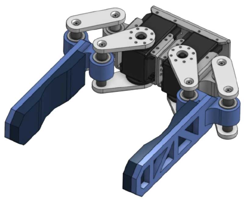
- In-Context Part Design 1 - Gripper Arm Also in addition to the instruction guide:
Gripper Arm/pad OnShape Model
- Change your tab title to the actual part name "Mechanical Gripper", rename your feature tree work with appropriate names,
- Create a description of the whole project (hint use PDF goals to summarize) for the whole project file using Main Menu (three thick horizontal bars)-Document Properties
- Name all of your features as you create them (only the ones you work on) including your part names
- Assign gripper arm appearance colour to # 1B5FAA (Blue) with a material Aluminum 6061 and gripper pad # DD5228 (red) with a material of Silicone Rubber,
- With completed gripper arm and pad on one side, use the given mid-plane in model assembly and the mirror tool, create/mirror the right gripper arm/pad components to end up with gripper arms on both sides,
- Create a standard 3 view ortho (correct front view placed) with dimensions and ISO using template mf-ANSI_A_MM.dwt set-up to maximize space to show left gripper arm (not including pad)
- Name bottom drawing tab: Gripper Arm (note you will have to delete some random empty text fields around the info block area as a result of template update)
- Drawing info block: You need to fill in the properties section of the part or sheet being used. For Materials see above model, Finish: Normal, Total Weight of part: (find by selecting your part in your model view, click on the small scale lower left corner, copy the weight in Grams and use the note tool on the drawing tab/ribbon to insert it into info block), Title (input in model properties under Title one), Part & Revision Number (input in deg properties), Checker and date, etc. (use note tool again) 6 mm for title, 3 mm to finish off info block
- Save your version titled FV1, put in the description section: summary of the whole project, the volume of the part, and five key things you learned in this project (bullets) using correct related terminology
- Fill in the OnShape Model/DWG Checklist sheet - self and peer (peers to mark only once if possible) and hand in the same time you share "Can Edit" with instructors email address (found bottom of all web pages here) for evaluation and feedback.
Gripper Arm OnShape Drawing
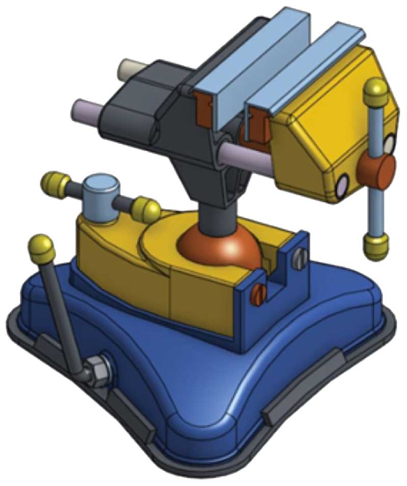
- In-Context Part Design 2 - Vice Plate Also in addition to the instruction guide:
Vice Plate OnShape Model
- Change your tab title to the actual part name "Swivel bench vice", rename your feature tree work with appropriate names,
- Create a description of the whole project (hint use PDF goals to summarize) for the whole project file using Main Menu (three thick horizontal bars)-Document Properties
- Create a mid-plane between your two inside vice ends then mirror new grip edge, overlap, and the two mounting screws,
- Using instruction image or full size image above, modify all colour appearances to your swivel vice assembly,
- Show ISO best fit view with default shaded view selected,
- Create a final version FV1, put in the description the total volume of your vice moving block only. Also include in the version description, the number/list of five key things you learned in this project using appropriate terminology
- Use the OnShape model checklist sheet to ensure you have completed the project correctly and remember to peer mark only once to ensure everyone gets that opportunity and not lose marks
4. Assemblies
This section introduces you to assemblies, sub assemblies, single documents, assembly mates, and an assembly design case study. Ensure you have reviewed the related video's in the Investigation section above before starting drawing projects below.

Drawing Project Instructions
Follow the instructions in the PDF's below to complete your drawing projects, remember log-on, proper file naming convention, and finish with final submission version fs1, and sharing for evaluation.
- Assembling In-Context Parts - Propeller Wind Belt Also in addition to the instruction guide:
Propeller Wind Belt OnShape Assembly
- Update your tab names to appropriate names and rename your feature tree work with appropriate names (mates not required),
- Create a description of the whole project (hint use PDF goals to summarize) for the whole project file using Main Menu (three thick horizontal bars)-Document Properties
- Assign belt appearance colour to # 000000 (Black) with a material "nylon",
- On your view object view options, select best ISO view with default shaded view,
- Create a final version FV1, put in the description the number of full turn revolutions the fan turns for the small pulley flag vertical to meet the angle and also the number/list of five key things you learned in this project using appropriate terminology
- Use the OnShape model checklist sheet to ensure you have completed the project correctly and remember to peer mark only once to ensure everyone gets that opportunity and not lose marks
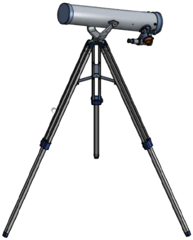
- Creating and Adding Sub-assemblies - Telescope Also in addition to the instruction guide:
Telescope OnShape Assembly
- Ensure you do complete step 8, and also select slider mate limits for Rack and Lens Mount and insert values of -2 inches for minimum and 0.5 inches for maximum
- Create a description of the whole project (hint use PDF goals to summarize) for the whole project file using Main Menu (three thick horizontal bars)-Document Properties
- Leave each of your worked-on sub assemblies and main assembly with best ISO view similar to sample telescope picture sample above,
- Create a final version FV1, put in the description how many of each of the mates you used and also the number/list of five key things you learned in this project using appropriate terminology
- Use the OnShape model checklist sheet to ensure you have completed the project correctly and remember to peer mark only once to ensure everyone gets that opportunity and not lose marks
5. Collaboration and PDM
This short section introduces you editing history, versioning, collaboration with simultaneous/branch editing, and working with existing CAD files. Ensure you have reviewed the related video's in the Investigation section above before starting drawing projects below.

Quad-copter Propellers

Headphone
Drawing Project Instructions
Follow the instructions in the PDF's below to complete your drawing projects, remember log-on, proper file naming convention, and finish with final submission version fs1, and sharing for evaluation.
Evaluation:
Complete all parts of the tutorials and web instructions properly for full marks. Fill out the OnShape model checklist or the OnShape Model/DWG Checklist depending on the project the same time you share with your instructor, to ensure you have completed all general requirements of project.

| Evaluation Breakdown Component Descriptions | Marks |
|---|---|
| Always double check that you have completed all components for full marks. | |
| 1-1 Basic Sketching - Completed link bracket tutorial & DWG | 40 |
| 1-2 Sketching in Context - Completed mould gasket tutorial | 15 |
| 2-1 Basic Features 1 - Completed cylinder tutorial & DWG | 40 |
| 2-2 Basic Features 2 - Completed water pitcher tutorial | 10 |
| 3-1 In-Context Part Design 1 - Completed gripper arm tutorial & DWG | 40 |
| 3-2 In-Context Part Design 2 - Completed vice plate tutorial | 20 |
| 4-1 Assembling In-Context Parts - Completed propeller belt tutorial | 20 |
| 4-2 Adding Sub-assemblies- Completed telescope tutorial | 20 |
| 5-1 Collaborative Editing - Completed headphone tutorial | 20 |
| 5-2 Working with Existing CAD Files - Completed quad-copter tutorial | 20 |
| Total Activity Marks | 140 |