Unit 2: Grade 10 Technological Design - Robotics - Technical Sketching
This unit will introduce you to communicating your ideas using technical sketching standards. Learning technique, format, methods will be practiced and then applied to a design challenge.
Course Units and Descriptions
Use this table for an overview and navigate to each of the course unit pages.
| Unit | Description |
|---|---|
| Review course outline for more details | |
| 1 | Careers & Safety- Intro, computers, organization, and careers |
| 2 | Technical Sketching- freehand sketching, ortho, dimensions, ISO views, custom ortho design |
| 3 | Basic 2D & 3D CAD Intro- 2D coordinates, lines, ortho views, 3D drawing, and custom design digitized |
| 4 | 3D Parametric Design- 2D sketch, 3D parts, feature tools, drawings, exporting for 3D printing |
| 5 | Sheet metal Design- thin material design, folds, assemblies, 2D print, project design, testing, and build |
| 6 | Robot Assembly- part reproduction, part assemblies, custom function design and build |
| 7 | Web Portfolio- Showcase course work, projects, and understanding with web portfolio and presentation |

Unit Content Activity Quick Links, Click to Jump to Specific Activity!
- Unit 2, Act. 1: Technical Sketching
- Eng. Communications, Sketching Intro, Sketching Tips, Ortho/ISO Intro, Selecting Front View for Ortho,
Ortho Creation Steps, Sketching Standards, Resource links, Common Mistakes,
(Create) Sketching Exercises, Ortho Note, ISO Challenge, Ortho Block Build Steps in Detail and Challenge, Evaluation - Unit 2, Act. 2: Custom Orthographic Design - Key Ring Accessory (KRA)
 Unit 2, Act. 1: Technical Sketching
Situation:
A class of students interested in the field of Engineering have taken a course to find out what Technology Design is all about. Coming up with solutions is what Engineers do on a daily bases. How they communicate those ideas is critical and one of those ways is with technical sketching.

Problem/Challenge:
Practice your sketching techniques with sketching practice assignments while learning about engineering drawing standards. As sketching is the fastest way to communicate, learn, and practice these standards, we will use several related assignments to fast forward our knowledge and skills to better prepare for application in CAD programs in the near future. These sketching projects will include:
- Basic sketching techniques
- Sketching basic shapes including wire-frame and isometric formats
- Selecting front view of an object
- Orthographic projection
- Sketching layout and line types
- Dimensioning object views
Related assignments will be found below in the Create & Construct section.
Investigation/Ideas:

Communicating Your Ideas As an Engineer Effectivly and Quickly
Communicating your ideas is key for Engineers and is a critical skill to learn. Technical sketching is used in all kinds of situations. Thumbnails are where ideas initially start... some of the greatest ideas started on a napkin in a restaurant for example. Full size sketches take a little more work and formality to the steps of creating a clean technical sketch. Best way to get started is to practice sketching simple line exercises, then basic shapes, then more complex shapes. After you feel comfortable with these sketching techniques, learning about orthographic drawings will help you effectively communicate your idea in detail through isolated views. This section will give you some more information on orthographic drawing process to use with your orthographic sketch exercises:
Sketching Introduction
Sketching is a very important skill to practice and develop. This is more commonly used in the traditional art areas, but still has a place in digital graphics to save time Sketching allows you to quickly generate visual graphic ideas on paper. There are several techniques that can help you build and develop your skills for sketching.

- pencil holding, spin, wrist, arm, shoulder
- Layout and organization
- weight light construction, heavy outlines
- base lines and straight lines
- clean curves, and smooth circles
- basic shapes 2D and 3D
- textures, shading and light sources
Here are some resources to check out showing how to build your sketching/drawing techniques and practice them:
- Drawing Practice
- * Using Wrist vs Shoulder
- Improve your Drawing
 Traditional Drawing Techniques 13.33
- Outlines, Edges, Shading 8.20
- Tablet sketching 10.01
- Sketching skills
- 10 Sketching exercises to Practice
- Interesting M, 10.01
- Basic Geometric Shapes 25.5
- Draw Anything with the help of basic shapes 14.14
- Additive And Subtractive Methods -hand 26.12
- Additive & Subtractive methods -tablet ...17.04 - 21.07
- Fundamentals: Shapes & Forms 15.59

Sketching Tips when Practice Sketching Assignments
- lettering sizing is generally 6 mm for titles, 3 mm for normal
- Using two parallel lines will ensure consistency and straightness
- speed will smooth out your lines (remember bicycle analogy)
- ensure circles are large (full size, using up most of the space)
- create circles using cross-hairs first, then marking space from centre, then smooth circle hitting all space marks
- try to keep page straight to practice different directions
- include all text and sketching for full marks, some forget to fill in the two key points below the title and reference
- don't erase, just keep practicing and use back or another sheet if necessary
- start a new sheet and keep your practice sheets together, with final (best one to be marked) at the front
- don't worry so much about stopping exactly at each corner of objects, focus on clean, straight, light and crisp lines
- If you mess up, practice on back and Astrix the ones you would rather the instructor mark
- for sketching 3D shapes, use a light construction line for the base line to help with shape creation
- for complex shapes, use additive or subtractive sketching methods - i.e. be aware of both sketching methods
Orthographic and Isometric Views and Sketching Techniques
Once you have the basic techniques of sketching practiced, continue to do so to refine and hone this key way that all engineers use as part of their communication and design process. Orthographic (ortho for short), oblique (OBL for short), and Isometric (ISO for short) are different types of views that are commonly used to communicate your ideas graphically and though sketching, this can be done relatively quickly, compared to using a CAD program. Therefore the next thing to look at is orthographic views and the engineering standards that are expected to be followed as an engineer to communicate their ideas using sketching as a quick means to do this.
Selecting Front View for an Orthographic(Ortho) Drawing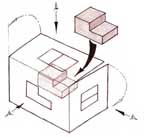
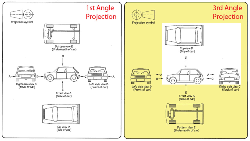
When deciding which view is to be used for the front view, three rules are used to determine this in the engineering field as a standard. The reason for these three rules is to prioritize and show the best views, create a standard set of views for any object, keep the view the least complicated, and make use the paper space standards, usually landscape. Objects in the real world, say for example a car has a front view, but the orthographic engineering front view most likely will be the drivers side in third angle project standard used here in North America. You must look at the object you are going to draw or sketch and decide which view shows the:
Three Rules for Selecting the Front View of an Orthograpic object
- Shows the most detail
- Shows the least amount of hidden lines
- Has it's length across the page (as layout is usually in landscape format)
In some cases, you may have a conflict with the rules and you will have to make a decision based on two or all three rules. Generally the most amount of detail will take precedence in most cases but not always. Be prepared to explain your selection of your front view if it is not a clear decision.
Practice View Selection
The following show a process of deciding on what the front view of an object is by using a quick prototype for spacial recognition if needed (in time, you can practice visualizing the different views in your head), then looking at possible views based on the three rules for selecting a front view to narrow down to a final decision on the front view
Spacial Rec.
1st possibility.
2nd possibility
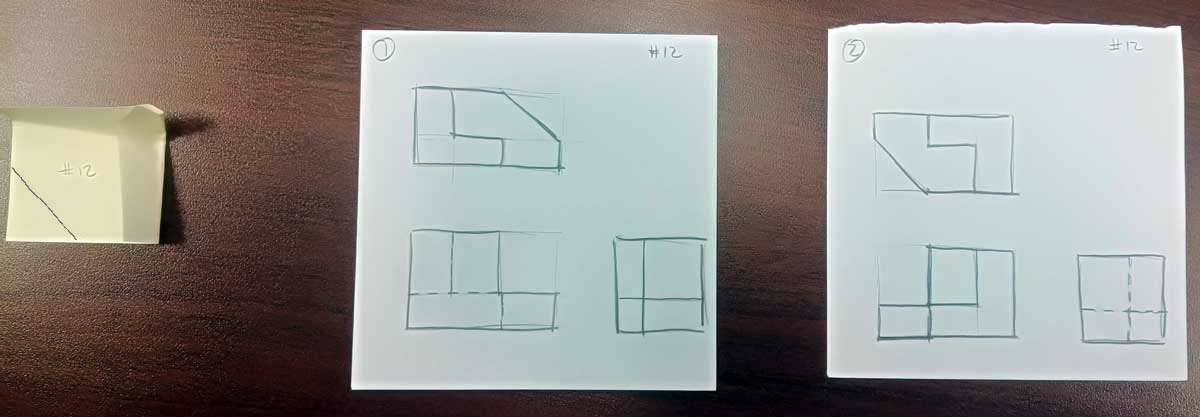
Visualize/prototype for front view
Looking at both possibilities above (small thumbnails), one more important point to keep in mind, the front view takes precedence in relaying the shape detail with respect to silhouette shape and showing less hidden lines when possible. In the case of sample above, less hidden lines in the 2nd possibility is the clear choice for the front view.
Once you have established the front view then you can be confident to sketch out the full page with the features, equal view spacing, dimensions, and isometric to create your ortho sketch as shown below.
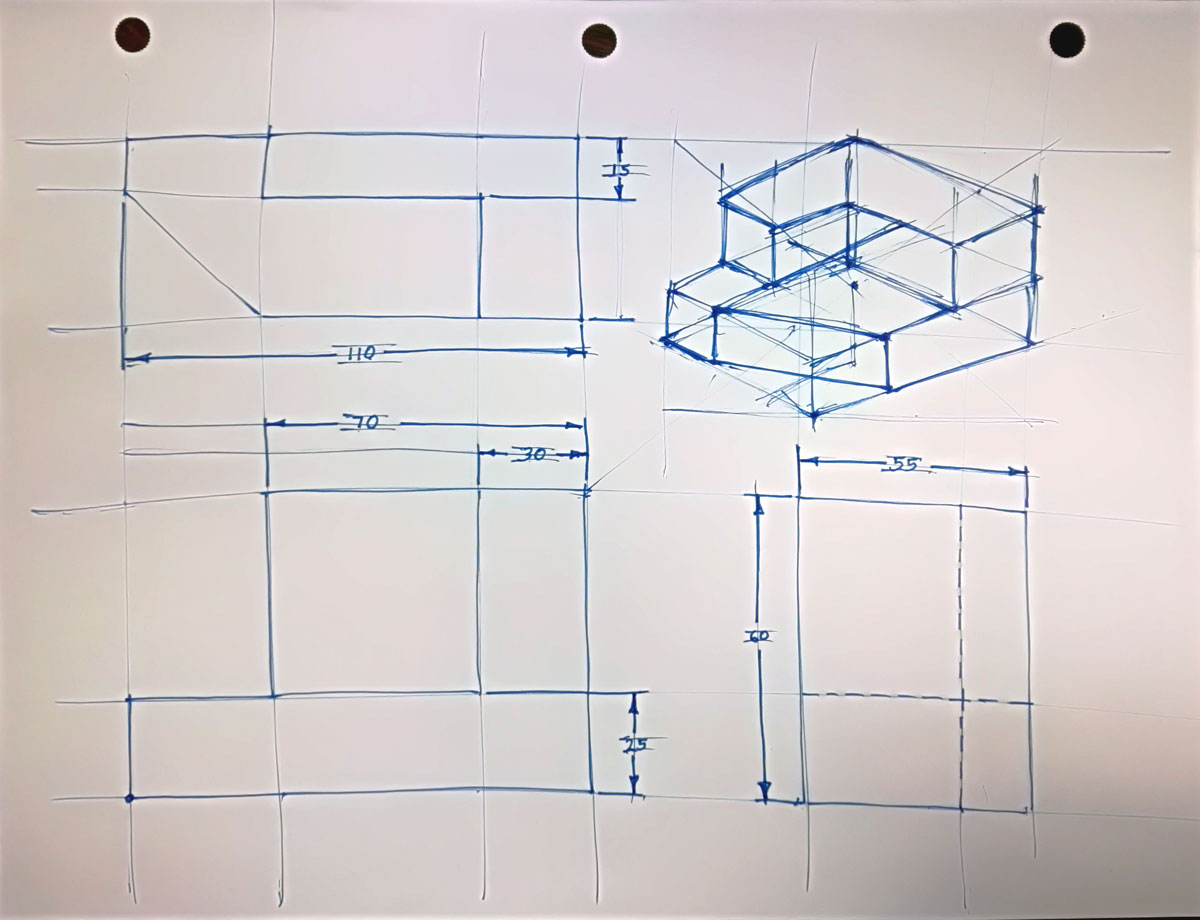
Layout & features
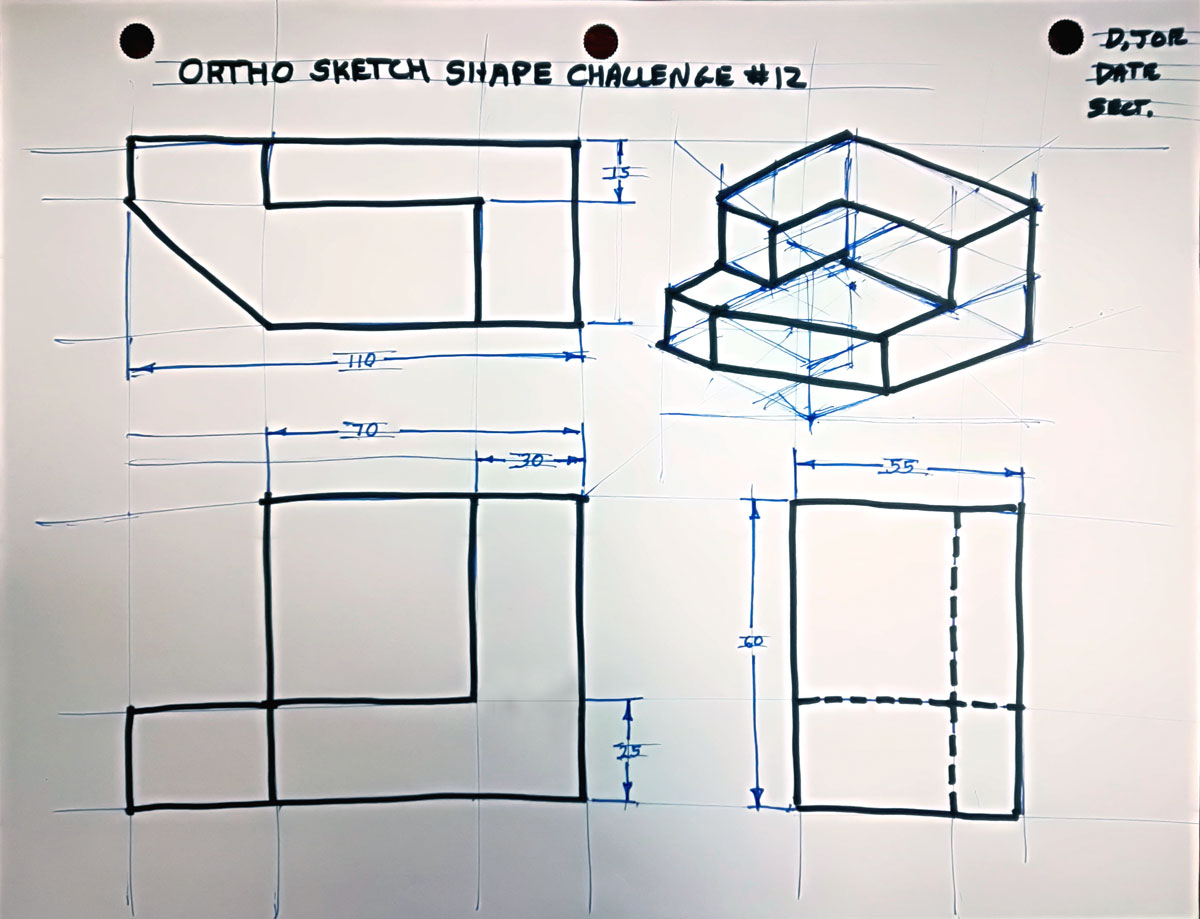
Object & Header
Orthographic Sketching Major Steps

By following these steps in order, will give you best results in a quick and efficient manner (remember class demo):
- Start by visualizing the approximate shape and size of your front view, and how much space needed for dimensioning
- Block in your views using construction lines starting with your front view, then your spacing, top view and right side view leaving room for your isometric view
- Block in your major view features using construction lines so that they will all align with each other
- Darken your object lines for all views including outline, features, and hidden lines
- Start dimensioning using construction lines to add ladder distances out from view envelopes 10 mm and 8 mm thereafter
- Ensure you are following dimensioning rules/standards in placement, locations, alignment, and spacing
- Create extension and dimension lines along with small thin arrows 2 mm thick by 3 mm long with dimensions 3 mm high
- Last, create your isometric by blocking in a wired cube/rectangle using additive/subtractive construction build sketch process with construction lines, then darken your object lines
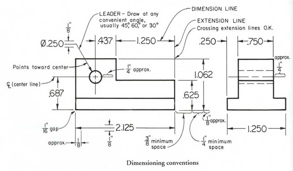
![]() Some points to keep in mind when dimensioning:
Some points to keep in mind when dimensioning:

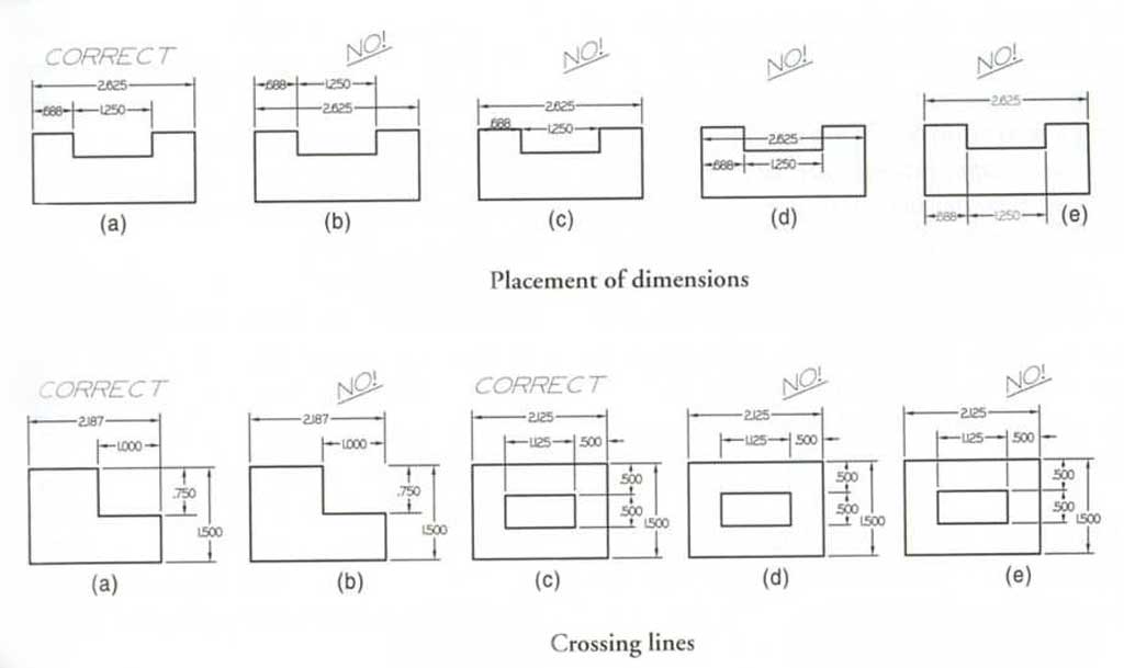
- Minimize the amount of dimensions to keep less cluttered
- Show overall and detailed dimensions to show feature locations and size
- Overall dimensions should be furthest out with detail dimension in between object view and overall
- Avoid placing dimensions on the actual view
- Avoid placing dimensions where dimension lines cross extension lines
- Extension lines may cross each other freely
- Extension lines may cross the lines of the drawing to dimension features properly
- Stay inside the envelope as much as possible
- Space the dimensions about 3/8" or 10 mm from the object and 1/4" or 6 mm apart thereafter
- Dimension on view that shows the feature best
- Draw all arrowheads about 1/8" or 3 mm long and very narrow
Sketching Standards
Below are some tips that you can use when sketching objects with orthographic views and dimensioning. You will want to review these and keep them in mind as we go further through the course including our CAD components as these principles and standards are what is used throughout the Engineering industry.

Line Types
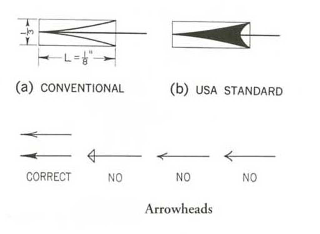
Arrows
Lettering
Dimensions 1
Dimensions 2
Resource Links

Below are several resources you may check out that relate to technical sketching:
- Process of tech-sketches, 4v
- Freehand lines & circles, 2.50
- 1st thing to draw, 18.57
 Sketching practice, s34
- What is sketching, s35
- Isometric projection theory
- The importance of sketching
- ISO sketching tut, 12.50
- Sketch an ISO Cube, 2.32
- Sketch ISO Circle, 3.24
- Sketch PVC connector, 8.25
 Engineering graphics, 35p
- Engineering Graphics, 119p
- Sketching index, 19v
- Third angle projection, 30.6
- Ortho projection, 6.40
- Third Angle Projection, 6.32
- Multi-view dwgs, 48s
- Engineering drawing, 136s
- Learning to draw buildings
- The process of architecture
- Sketch-a-day
- General drawing tutorials
- Drawing fundamentals
- Dimensioning & toll. ppt 94s
- Dimensioning ppt 73s
Common Mistakes When Sketching Orthographic Views of Objects
Some common mistakes students make when sketching objects for orthographic views are:
- Not selecting the correct front view, review and apply all three rules for selecting front view
- Sketching relative sizes to dimensions of object or object features
- Not aligning object views and/or also feature details in each view -use construction lines to line up
- Ensure arrow sizes are thinner, ratio of 2:3 - width to length, and ensure they are touching extension lines
- Line weights are not correct, remember construction lines are light and thin to show build of sketch, object lines are thick dark showing object views, dimension lines are thin with a medium weight and include an open gap in centre for the actual dimension which is always written the same direction as page view orientation
Create/Construct:

Sketching Exercises
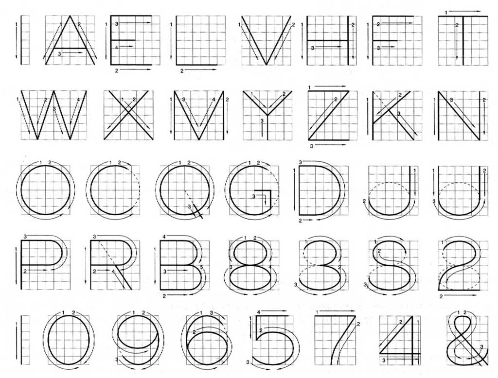
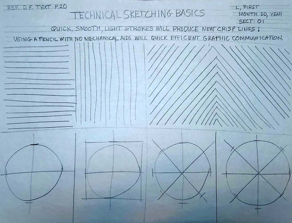
The following technical freehand sketching basics and sketching shape assignments are to be practiced in class and handed in for check, before moving on to the next sketch assignment. You are to practice using proper sketching techniques and reproduce what is shown including header, titles, notes, line work, and shapes. To get you started keep in mind the following points:
- HB or slightly harder (lighter) regular or mechanical sharp pencil is to be used
- No straight edges or rulers are allowed, this is all freehand
- Plan out page with light construction lines
- Review notes in header, but complete header last, as you may want to practice on several sheets first to practice
- With shapes, use light construction lines first, then go over with medium to heavy weight after, so there must be evidence of both line types for each shape you draw - i.e. don't erase your construction lines as they are worth marks
- Use your whole shoulder/arm and not your wrist to sketch crisp, clean, straight lines - see video resources and in-class demo
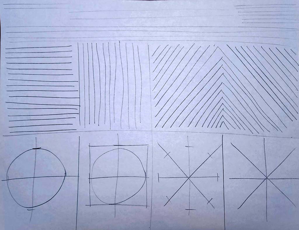
- Circles in first practice require distance ticks put in first to practice and train your hand/eye co-ordination and ensure circles are as smooth, round, and connecting on those ticks as much as possible,
 faster will get a smoother circle - use "air guitar" practice before touchng paper with pencil, as shown with in-class demo
 - 3D shapes, start with a light horizontal construction line, as the base line
You will need blank paper, pencil, and white eraser to complete the following assignments.
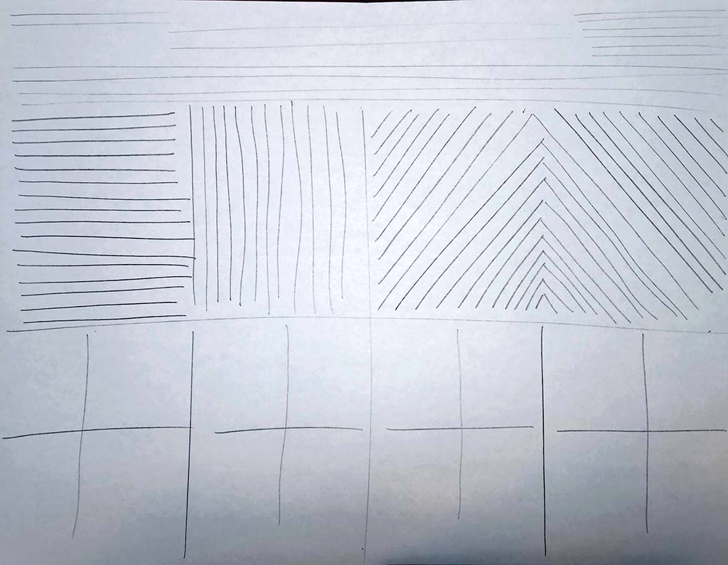
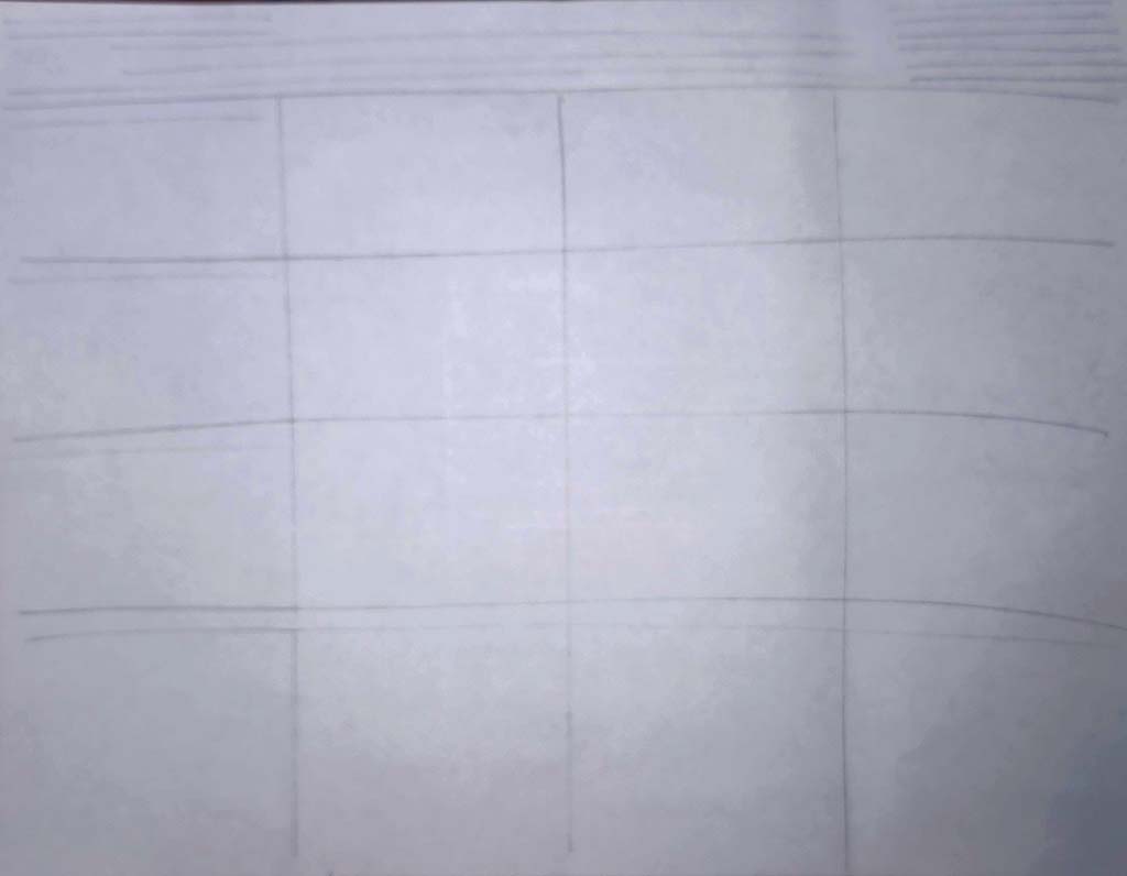
Sketching Basic Lines Practice
Whenever doing a technical sketch, always good to layout your page with what you are going to sketch, in this case, you need space for a header, and then divide up the rest of the page into quarters, then use some guidelines - about 3 mm for regular capitol block text and 6 mm for titles of information on page. Paying close attention to the demonstration will help with your sketching technique such as making relatively straight crisp clean lines. You will probably want to practice on a scrap piece of paper first to get the hang of using the proper technical sketching techniques before making your ![]() final Sketching Basic Lines practice sheet.
final Sketching Basic Lines practice sheet.
Page Layout
Lines
Circles
Block Text
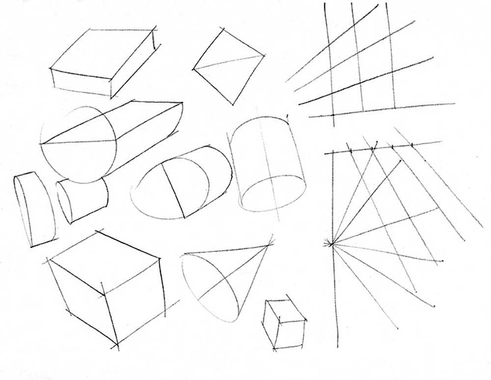
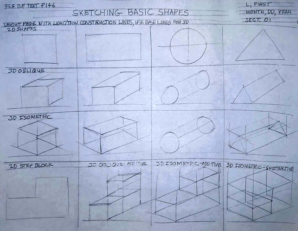
Sketching Basic Shapes Practice
This sketch is even more critical to layout using light/thin construction lines to locate space for a header, and then divide up the rest of the page into a grid of squares, then use some guidelines - about 3 mm for regular capitol block text and 6 mm for titles of information to locate on the page. Ensure you watch closely the demonstration, as it will help with your sketching technique to create 2D, 3D shapes using a baseline, 30 degree angle creation, additive, and subtractive methods. You will want to practice before making your final Sketching Basic Shapes practice sheet, so that you can be more confident in your sketching. This assignment includes two line weights using light/thin construction lines to start and finish with thick/dark object lines for your ![]() final Sketching Basic Shapes practice sheet.
final Sketching Basic Shapes practice sheet.
Page Layout
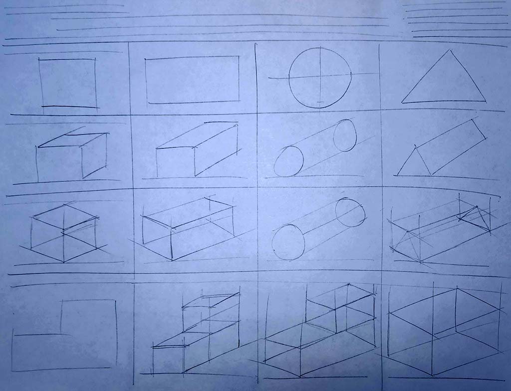
Basic Shapes
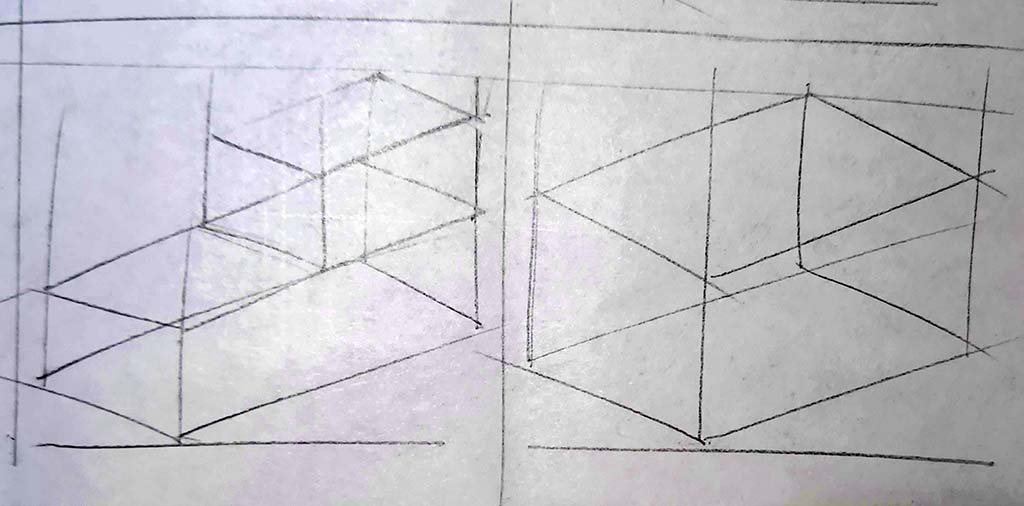
Add/Subtractive 2
Block Text
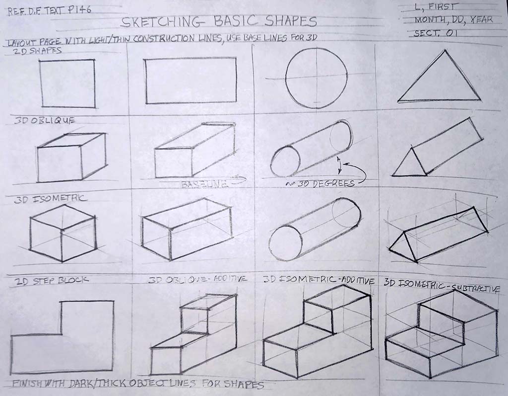
Thick/dark Lines
When you are done, follow the proper paper to digitization process and use Adobe Scan or a similar App in proper lighting to capture clear contrast of your completed sketches, to hand in work properly. Remember it is your responsibility to properly digitize and submit work properly, so if unsure click this link for a refresher on steps and more info!
Sketching Tips
- lettering sizing is generally 6 mm for titles, 3 mm for normal
- Using two parallel lines will ensure consistency and straightness
- speed will smooth out your lines (remember bicycle analogy)
- ensure circles are large (full size, using up most of the space)
- create circles using cross-hairs first, then marking space from centre, then smooth circle hitting all space marks
- try to keep page straight to practice different directions
- include all text and sketching for full marks,some forget to fill in the two key points below the title and reference
- don't erase, just keep practicing and use back or another sheet if necessary
- start a new sheet and staple all of your practice sheets together, with final (best one to be marked) at the front
- don't worry so much about stopping exactly at each corner of objects
- practice on back and Astrix the ones you would rather the instructor mark
- making shapes a light construction line for the base line will help with shape creation
- for complex shapes, use additive or subtractive sketching methods
Orthographic Communication with Sketching
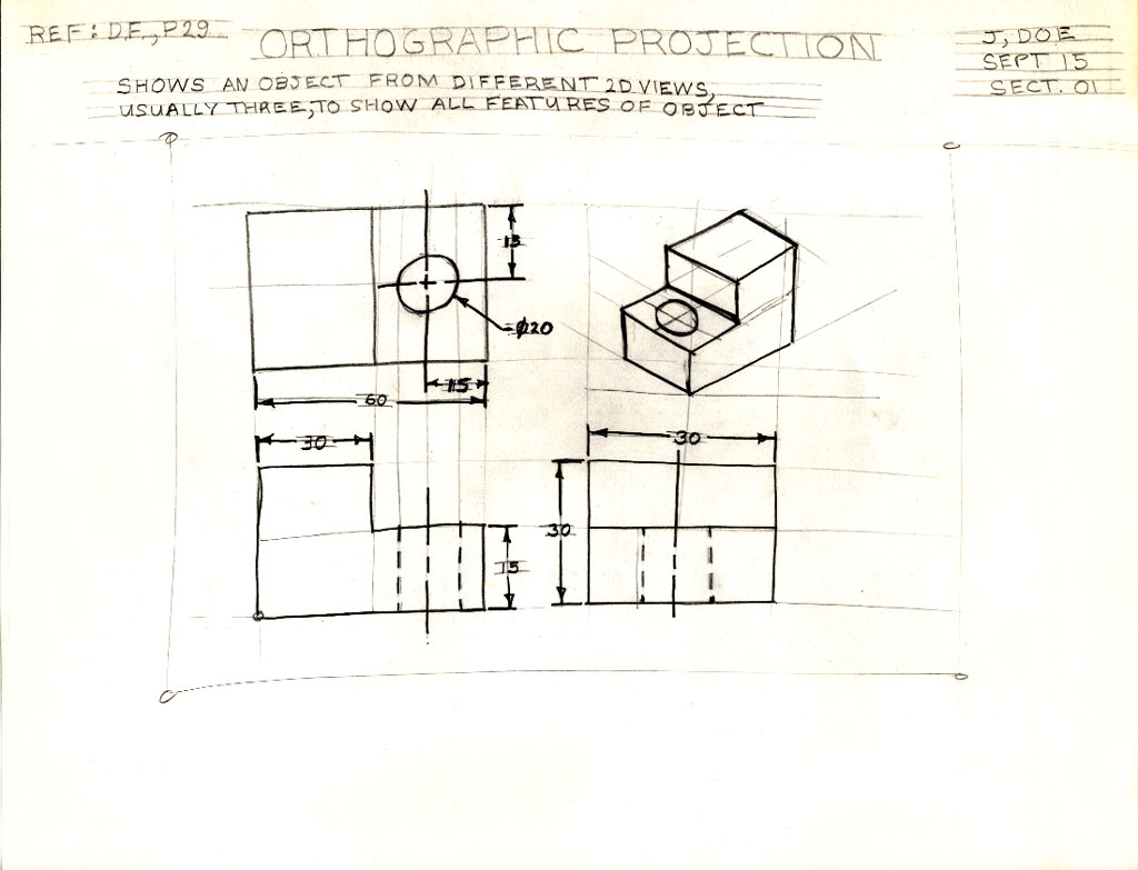
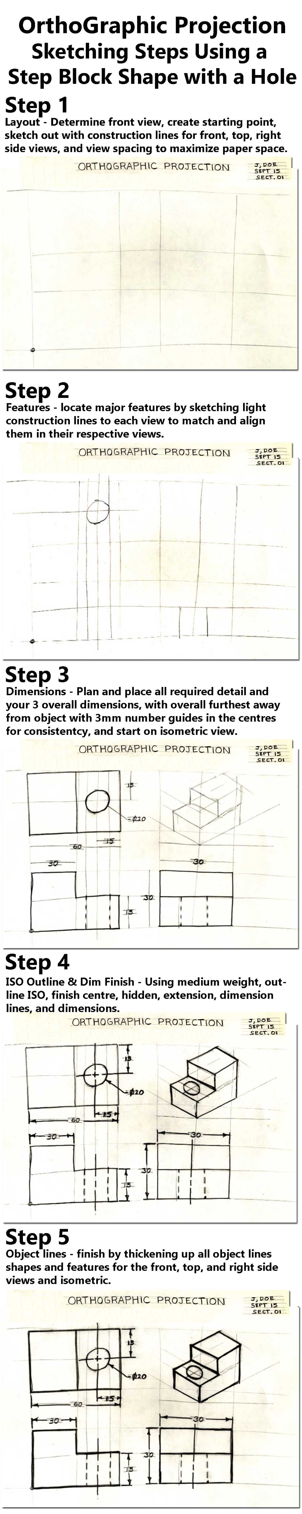
Below, ![]() 1 - 7 is a orthographic note, shows in order of creation, from layout, blocking in views, dimensioning, to a finished sketch. The following images below show a third angle projected orthographic sketch, dimensions, and isometric using a simple "step block" shape with a circular hole going through the center of the bottom step. In-class instruction will take you through the following steps in detail, so you can apply your new learning to other shapes.
1 - 7 is a orthographic note, shows in order of creation, from layout, blocking in views, dimensioning, to a finished sketch. The following images below show a third angle projected orthographic sketch, dimensions, and isometric using a simple "step block" shape with a circular hole going through the center of the bottom step. In-class instruction will take you through the following steps in detail, so you can apply your new learning to other shapes.
Ortho Graphic Object Short/Quick Steps
![]() See Ortho Block Build Steps in Detail further down below, for specific detailed instruction for each page/step to complete, and remember to take picture of each step for evidence of proper steps/build of Ortho Note.
See Ortho Block Build Steps in Detail further down below, for specific detailed instruction for each page/step to complete, and remember to take picture of each step for evidence of proper steps/build of Ortho Note.
- Using a full blank page in landscape format, (more details in the ideas/investigation section above for more support) start sketching the layout comprised of the header space (create light guidelines for all of your text to put in for later), ortho starting point and views (remember to maximize paper space and take in consideration the shape, size, scale, and spacing) using light construction lines as learned in the previous sketching assignments (Note: your front view and layout have already been identified for you when completing this graphic note, but in the future you will need to figure this out on your own)
- Next is to add some more light construction lines through both views that locate and align those features and then lightly sketch those in - such as the step and hole features
- Once the views and the features are lightly sketched in, plan and locate your dimensions keeping in mind dimension rules and standards by using 3 mm guidelines located 1 cm away in the centre of feature you are dimensioning. Once you have located all your dimensions block in your third quadrant (the empty space top right) to sketch in your best view isometric, all still with light construction lines
- Finish lines by using 2nd stage sketching by going over the different lines with the appropriate line thickness and hardness, object lines are a heavy weight - thick and dark, while dimension lines are medium weight - thinner and darker than construction lines
- This is your ortho shape finished
- Because this is a graphic note with space around the outside of our sketched ortho page, you are to fill in the labels, technical terms, and explanations, then fill in your text in your header using your guidelines previously made in step 1
- This step shows all of the labels in colour, a little easier to read, but not necessary. Last step is on the back copy the section below titled "Selecting Front View" with the three rules for selecting a front view, add a title "Five Steps building an Orthographic Sketch" with five single line points on those steps in your own words, then have a partner review it for any missing components or mistakes prior to handing in for a mark


7, Labels done
(only for info)
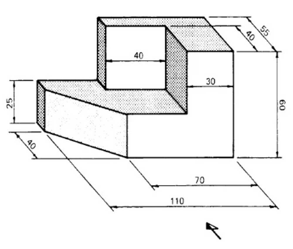
10 Block Challenges
Ortho-Practice
ISO Block Challenge Support:
5A, 5B, (0-60%)
6A, 6B, (60-70%)
7A, 7B, (70-80%)
8A, 8B, (80-90%)
9A, 9B, (90-100%)
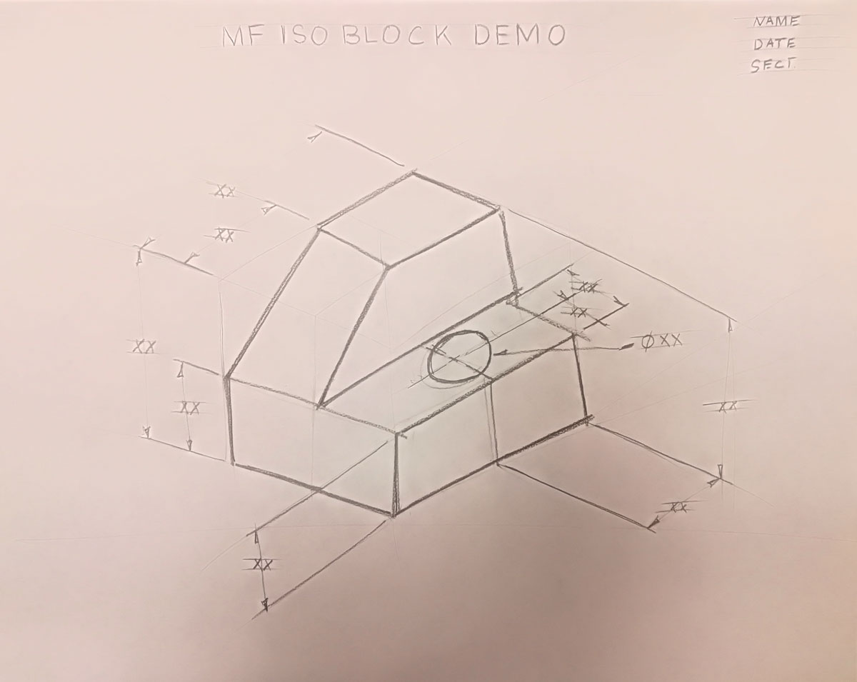
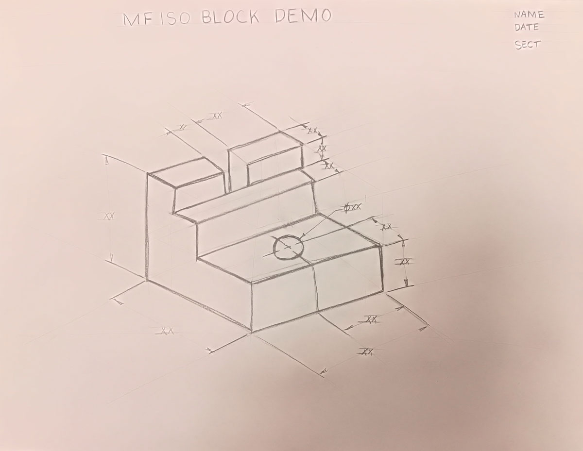
ISO Full Page Build Practice for the Ortho Block Sketch Challenge
Two Full Page ISO Block Objects with ISO Aligned Dimensions
Sample Block ISO 1
Sample Block ISO 2
With the 10 ortho block challenges above, select a matched skil-leveled block sample at your current grade level/difficulty (recommend a level 5 for a student with 0-60%, level 6 for 60-70%, level 7 for 70-80%, etc) and create a full page sketch ISO showing best view with all dimensions needed to later complete a ortho sketch challenge. Use the sketching techniques and information you learned in your practice sketches and Ortho note, to further practice, refine, and demonstrate your new sketching abilities, knowledge of lines, shapes, and your recent Orthographic note, to show your new technical skills and knowledge. Remember while sketching an isometric view of of your block to use additive and subtractive sketching/build methods after laying out the page.
- Layout with a 1 inch header for title of your ISO block and your name/date/section with 3, 6 mm guidelines
- Do the cross method to find centre of page with construction lines
- Using ISO angles and keeping in mind to fill the page with your object and dimension, from the centre use half the length (lean), half the width, and half the height to find your baseline and start point for your ISO
- Build your ISO using additive and/or subtractive sketching methods to complete your ISO
- Use a ruler to measure your block to place those dimensions on your ISO view
- Using same dimension rules from the ortho note and aligning with your current ISO lines, plan, organize, and place your overall and detail dimensions for your ISO
Ortho Block Sketch Build Steps in Detail, To Apply to an Object Ortho Block Challenge
Follow the same steps as above, steps 1 to 5 (our in-class lesson/demo graphic note) to correctly apply your new leaning to a new ortho block object sketch challenge. An ![]() orthographic summary sheet, sample, rubric, with checklist is to be used to assist with your practice and process. Students are to use the Ortho Sketch Self-Peer Checklist with a peer to insure you're on the right track in completing the ortho block challenge. Below are the steps broken down into further detail:
orthographic summary sheet, sample, rubric, with checklist is to be used to assist with your practice and process. Students are to use the Ortho Sketch Self-Peer Checklist with a peer to insure you're on the right track in completing the ortho block challenge. Below are the steps broken down into further detail:
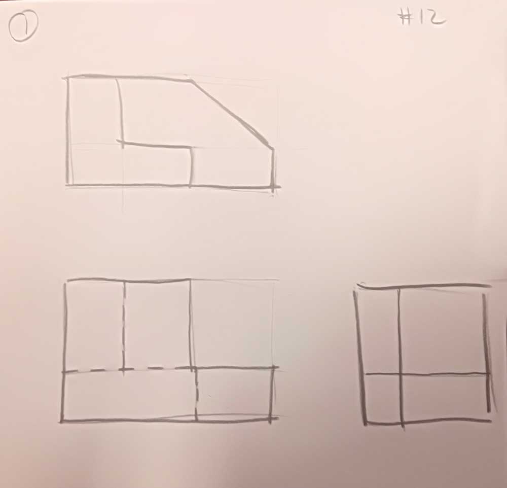
- Step 1, Layout: Start with the layout using light construction lines to locate the header and then the ortho start point, then using the three rules, decide on the front view of your object, so you know what to frame in for your major view shapes and sketch-in equal spaces between the front and top, and front and side view, keeping in mind the amount of dimension rows you will need between views, and keeping the object view sizes relative to each other (scale to fit), all at the same time ensuring you maximize/use your full paper space and that your views match the objects dimensions
- Step 2, Features: Sketch in with light construction lines, your major object detail features from your front view to both your top and right-side view, ensuring that they are relatively straight and aligned in each of the views
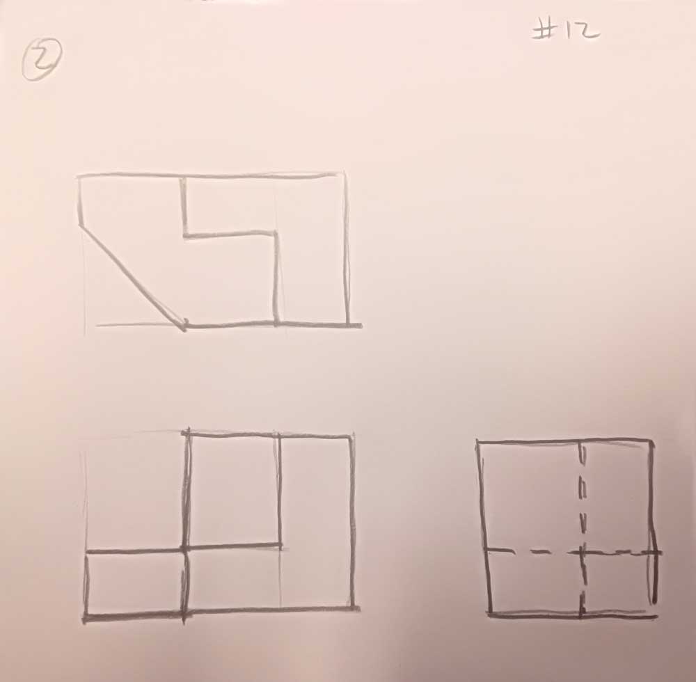
- Step 3, Dimension Lines: Use a middle weight line to show your orthographic object view outlines, feature details, and hidden feature lines, then plan, decide, and place your dimension lines using light construction lines, keeping in mind 6 things: 1) dimensions not to be placed outside the drawing envelope and keep them outside the view envelope, 2) dimension spacing levels out are 10 mm and 8 mm thereafter, 3) must have three overall dimensions, 4) Place detail dimensions where that feature is most easily seen, 5) align and group dimensions where possible for organization and ease of view, 6) and have enough detail dimensions for someone to build or make this object ensuring no duplication or un-necessary ones, keeping detail dimensions to a minimum always review/double check your dimensions, engineering dimensioning standards for proper dimensioning, then add some 3 mm dimension guidelines for dimension numbers, generally in the centre of each dimension line in a horizontal format, and fill in the dimension numbers, lastly now knowing your available space block in the third quadrant, you can centre and locate your baseline Isometric start point and build your ISO wireframe using 30 degree parallel lines and additive and/or subtractive methods with light construction lines
- Step 4, Extension and Dimension Lines to Mid Weight: Sketch in any possible centre lines, then your extension and dimension lines with a mid weight, leaving about a 2 mm gap from the object and going past the last dimension line about 2 mm, ensure you are taking in account the engineering dimension standards with how extension lines are to be put in (see Dimension Standards 1 and 2 illustration above for examples), then use a mid weight line to show your Iso view
- Step 5, Object lines: Flatten your pencil lead end to create your final object views (object outline and feature lines) with thick dark lines, about 0.7 mm thick, at the same time refining your lines to look their consistent best, starting (for right handed people) the top left working your way down/across to bottom right, to minimizing the smudging of your lead on your paper
![]() Use your sketching techniques you learned above while you sketch your ortho block challenge out and remember to review the tips in the Investigation /Ideas section for detailed support. Also, collaborate with partners with your selection of your front view of your object, just in case you missed something, as drawing the wrong front view will compound your mark lower.
Use your sketching techniques you learned above while you sketch your ortho block challenge out and remember to review the tips in the Investigation /Ideas section for detailed support. Also, collaborate with partners with your selection of your front view of your object, just in case you missed something, as drawing the wrong front view will compound your mark lower.
Evaluation:
Ensure that you have completed the Sketch Ortho Self-Peer Checklist and attach the back of your completed custom ortho block sketch project. Be aware that your self and peer evaluation marks may be used also for an individual mark based on how close you are to the teachers evaluation. For this reason, ensure that your peer marker has not marked someone else, so that everyone gets an opportunity to peer mark. Peer markers that peer mark twice will lose marks on their lower peer mark entry.
Here are some student samples with teacher feedback and marks in ![]() PDF's; Sketching Basics, Sketching Shapes, and Sketching Ortho Projection Demo, Sketching Ortho Custom Blocks, Sketching Ortho Custom Blocks 2 with Eval's.
PDF's; Sketching Basics, Sketching Shapes, and Sketching Ortho Projection Demo, Sketching Ortho Custom Blocks, Sketching Ortho Custom Blocks 2 with Eval's.

| Evaluation Breakdown Component Descriptions | Marks |
|---|---|
| Always double check that you have completed all components for full marks. | |
| Sketching Basics - clean, straight lines, and smooth round circle curves | 10 |
| Sketching Shapes - clear shapes sketched with correct angles, lines, and shapes | 15 |
| Orthographic Sketch Note - 3 ortho views, 1 ISO, dimensions, and labels | 30 |
| ISO Sketch & Dim - Centred full page ISO sketch with dimensions | 20 |
| Orthographic Sketch Challenge - 3 ortho views, 1 ISO, Dim, & S/P Eval. | 30 |
Unit 2, Act. 2: Custom Orthographic Design - Key Ring Accessory
Situation:
A class of students interested in the field of Engineering have taken a course to find out what Technology Design is all about. One of the major principals of this course/field is the "Design Process". Coming up with solutions is what Engineers do on a daily bases.
Problem/Challenge:

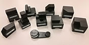
There is a three parts to this activity, with the first part understanding the design process and identifying the steps on different tasks/challenges such as coming up with ideas for a Key ring accessory using this process. Your task is to use the design process model, SPICE to design a practical/decorative key ring accessory to be later drawn in CAD and printed in 3D using our 3D printer. A hidden aspect of this activity is also to practice and show your sketching ability for creating thumbnail ideas, and also creating an orthographic with dimensions and isometric of your idea. The key chain accessory itself has specific requirements which is to include:
- A design that is unique to you, custom, practical and/or decorative, and related to technology
- Approximately sized to a standard Staedtler white eraser (60x20x10mm)
- Have at least one non-cylindrical and one cylindrical main feature (in-addition to hole), with no sharp edges
- Key ring hole must have a minimum 4 mm diameter, at least 4 mm support material around the hole, with a minimum 4 mm overall thickness
You will need to explain the SPICE design process steps first in how it is applied to the key ring accessory, before actually starting to design it. The following are the major steps for this project:
- Start by explaining filling in the steps of SPICE explained in terms of this project, the key chain accessory design
- Create five different isometric thumbnail ideas based on above parameters with each idea labeled, filling the page
- A final full-page scaled orthographic sketch showing minimum dimensions and an isometric view as previously practiced

Investigation/Ideas:
A design process is what engineers, entrepreneurial, inventors, etc. use or go through to come up with great solutions to resolve or find solutions to problems. Some starting points to coming up with ideas are:
- Use your own experiences, knowledge, and interests
- Talk to your peers, friends, and/or professionals
- Research using Internet, related magazines/books, and/or similar sources
- Actual ideas already completed that you could use to make it your own
There are many design process models out there, some very long and detailed wile others simple and short. Most successful corporations will already have a process that employees must follow while working which involves reporting on those steps taken. We will look at some of these models and focus in on one specifically called SPICE to show how the technical design process works and also below are some more support links on thumbnail sketching:

- SPICE Design Process Model (We will be using this model)
- A detailed look on each stage of designing
- Six Models of the Design Process
- The Engineering Design Process
- Sketching - the visual thinking power tool
- Sketching -design process to the next level
- Lost Art of Thumbnail Sketches
- Examples of thumbnail sketches
- Sketching with a purpose
- Thumbnail sketching shoes, 3.03
- Thumbnail sketches - Architecture, 12.16
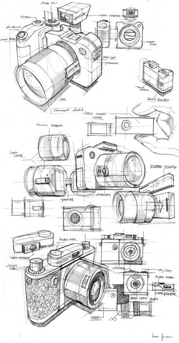
Samples of Work
The following samples show what thumbnails would look like and how your orthographic sketches would look like when applied to other designs such as key ring accessory project. You can also check out these past student thumbnails and final ortho sketch designs.
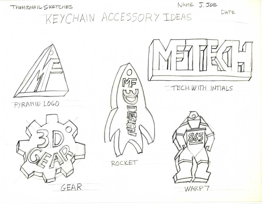
Thumbnails
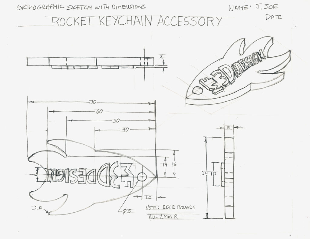
Ortho 1
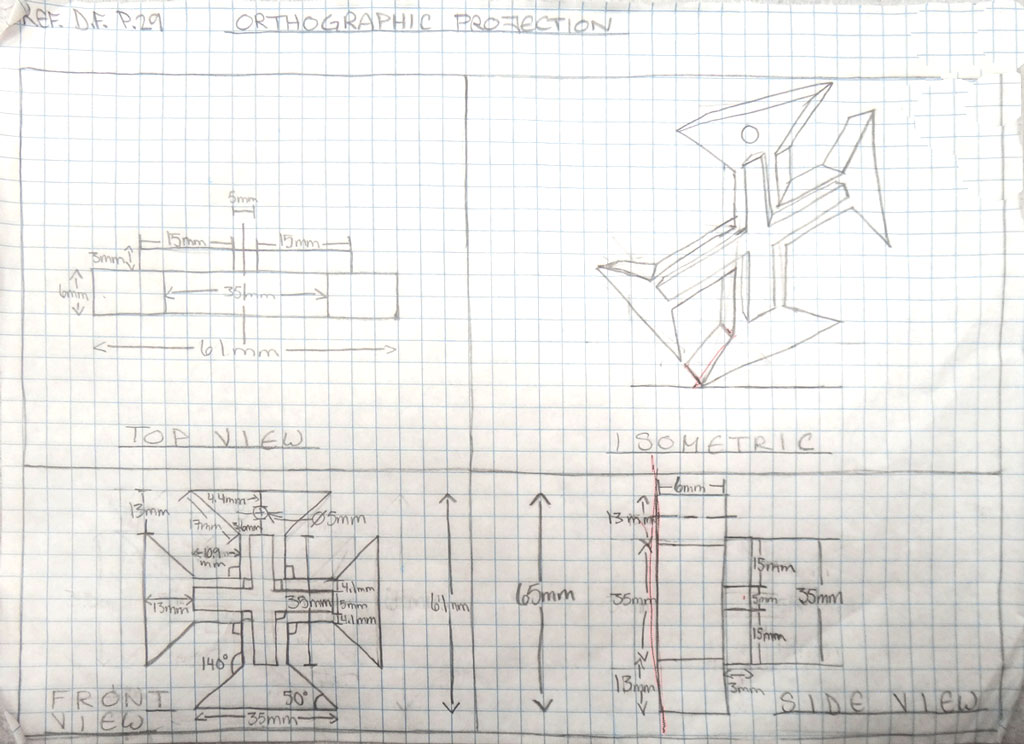
Ortho 2-3D CAD
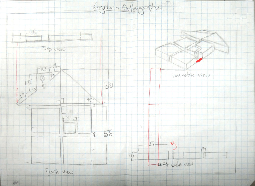
Ortho 3 - 3D Print
Create/Construct:

Steps To Complete the Key Ring Accessory (KRA)
- Using the handout SPICE Applied to the Key Ring Accessory, fill in each of the steps, using your understanding of this project and how it applies to SPICE, then save as a PDF to peer take-up in class and then submit for marks
- Investigate and research to come up with working ideas that you can design and later 3D print
- Use a full page with large isometric thumbnails to show your designs based on the requirements, showing hole location, and have each labeled with descriptive notation and identify the one you think will be your final design
- With your final design decided, and approved by your teacher, draw a scaled orthographic (i.e. to fill the page with space for dimensions) showing the correct front, top, and right side view using your recent experience from the previous ortho practice challenge
- When you are done, use the Sketch Ortho Self-Peer Checklist to check that your sketch is done correctly by completing the self-evaluation column and then combine to your final ortho sketch PDF as one file, with your ortho sketch as page 1 and your self/peer checklist as page 2
- Send your Ortho and Eval combined PDF single file to your partner to have it peermarked - i.e. highlight issues and insert marks in the Peer Eval column for the respective weighted categories
- Submit to Google Classroom before due date
- Save a JPG image of your KRA ortho sketch and resize in your preferred image editor making it a size width of 110 pixel wide with locked aspect ratio corresponding height at 72 DPI resolution. Using Jamboard class share insert your reduced image as close to the centre and to the top of the page, and put your last initial, first name at the top with a text size reduced to Caption size, to showcase your idea
Evaluation:
You will be evaluated on your SPICE key ring accessory explanation, thumbnails, and final orthographic design. Here are some student samples with teacher feedback and marks ![]() KRA final ortho sample 1, sample 2. A breakdown of those marks are below:
KRA final ortho sample 1, sample 2. A breakdown of those marks are below:

| Evaluation Breakdown Component Descriptions | Marks |
|---|---|
| Always double check that you have completed all components for full marks. | |
| SPICE - SPICE design process steps based on the key ring accessory | 14 |
| Thumbnails - Layout for five ISO thumbnails, full page with holes, notations, and labels | 15 |
| Orthographic - Sketch showing final design with 3 views, dimensions, and ISO | 30 |
| JamBoard - Place your final KRA Ortho in the class KRA JamBoard | 10 |
Emergency Supply Teacher Instructions
In case of emergency, students can download the Matching Isometric with Ortho-Graphic View 1 challenge and complete using Adobe Acrobot Reader DC commenting tools (already installed on computers) for 12 marks. Next, they can work on Surface Identification Counter Clamp Bar Challenge again using the Adobe Acrobot DC commenting tools to fil in the answers for 30 marks. Students will be asked next day to submit after take-up and review in class.