Unit 5: Grade 10 Technological Design - Robotics - Sheetmetal Design
This unit will introduce you to SolidWorks sheet metal creation. This type of tool comes with several unique tools that work best with sheet metal designs. Creating sheet metal parts with SolidWorks is an important aspect of the program as this is a commonly used process in industry. Creating a sheet metal part can also be later flattened to see the pattern if the sheet metal part were all unbent and flattened out.
Course Units and Descriptions
Use this table for an overview and navigate to each of the course unit pages.
| Unit | Description |
|---|---|
| Review course outline for more details | |
| 1 | Careers & Safety- Intro, computers, organization, and careers |
| 2 | Technical Sketching- freehand sketching, ortho, dimensions, ISO views, custom ortho design |
| 3 | Basic 2D & 3D CAD Intro- 2D coordinates, lines, ortho views, 3D drawing, and custom design digitized |
| 4 | 3D Parametric Design- 2D sketch, 3D parts, feature tools, drawings, exporting for 3D printing |
| 5 | Sheet metal Design- thin material design, folds, assemblies, 2D print, project design, testing, and build |
| 6 | Robot Assembly- part reproduction, part assemblies, custom function design and build |
| 7 | Web Portfolio- Showcase course work, projects, and understanding with web portfolio and presentation |
Unit Content Activity Quick Links, Click to Jump to Specific Activity!

 Unit 5, Act. 1: Introduction to Sheet Metal in SolidWorks
Situation:
Design and creating robots and similar mechanical components in Technological Design, sheet metal (SM) is commonly used. Using sheet metal to create bodies to support mechanisms is easier, lighter, and more efficient. For this reason 3D CAD programs need to be able to work with sheet metal in a virtual environment to create working designs that can be used for building and supporting mechanisms for the goal of the machine designed. Engineers use the Feature Sheet Metal tool set to create these designs using a set of related tools specifically designed to support the engineer to design and the manufacture to be able to build these machines made from sheet metal.
Problem/Challenge:
You are to explore the different methods of creating a sheet metal parts from a closed profile, open profile, and a solid material. Familiarizing yourself with the different tools through presentation and practice, then creating simple sheet metal parts, the 2 hole clip, a simple open box, and a final custom box with lid. Sheet metal parts will have drawings with orthographic views with proper placement of the front view, appropriate dimensions placed, isometric, and flat pattern shown. The final custom box will also be printed and built as a prototype.
Investigation/Ideas:

Sheet Metal Introduction
A great introduction to sheet metal with SolidWorks should be reviewed. Being aware of the different characteristics of sheet metal, its manufacturing process, and advantages of using it, you will be able to design some effective and practical designs.
Sheet Metal in SolidWorks
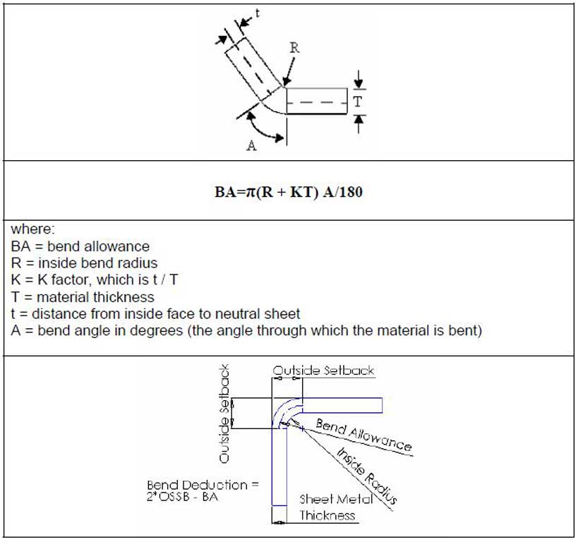
 The Sheet Metal feature tools in SolidWorks, works with the basic characteristics of a thickness gauge of flat material with the ability to make and control bends. SolidWorks has built in gauge tables for thicknesses for different materials and your own custom tables can also be added. Bends tables are also provided to automatically calculate the standard bend radius and bend allowance based on material, thickness, bend radii, and bend angles, but custom bend tables can also be added.
When edges are bent, spacing and relief cuts with different shape options need to be considered. The spacing may be for clearance for the bend itself or you may want a gap for a weld to support and strengthen the design. A powerful option that SolidWorks offers, is to flatten your design so that the manufacture can cut out the pattern. Once the pattern is cut out, there may be additional holes, cut-outs, miters, and press forming prior to the bending, which may include simple straight bends, edge flanges, corner treatment, hems, rolls, lofts.
Key Terms
The following are some common sheet metal feature tools that could be used with your design creation.
- Base Flange - creates sheet metal part from both open and closed sketches
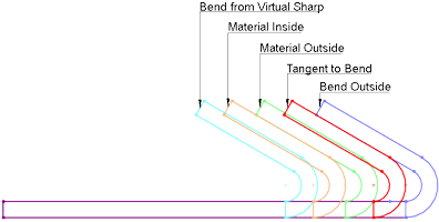
- Edge Flange - adds a flange that extends from existing model edge with alignment options Material Inside, Outside, and Bend Outside and relief cuts Tear, Rectangular, and Obround
- Mitre Flange - similar to Edge Flange, but are made with a cross section open sketch and will automatically mitre corners
- Hems - simple feature to strengthen edges created with a number of parameters in the property manager
- Swept Flange - open profile perpendicular to a custom pathway of lines and/or arcs to create a sheet metal part
- Forming Tool - is a mould to re-use through your SW Design Library to create unflattened features/shapes on your sheet metal part
- Sketched Bends - allows you to draw a line on a flat closed profile and bend it on that line and should be careful with alignment options
- Flatten - see your folded design in flattened state and be aware that flattened operations do not propagate back to the formed state
- Unfold/Fold - if you need to complete edits or operations, use this tool rather than the flatten tool, so that
- Rip & Insert Bends - starting with thin geometry based on extrudes and shells, you can manually convert to sheet metal with bend locations and rip or separation sections
- Lofted Bends - using two open 2D open profiles, create a smooth transition from one shape to the other

Resources
The following support links are great resources on sheet metal (SM) tools and related information for use with SolidWorks (SW).

 SW Sheet Metal Intro PPT, 42s
 Intro to SW Sheet Metal
 Introduction to SM, Play list
- SM Open/closed profiles, 8.01
- SW Sheet Metal Design, 59s
- SW Help on SM
- Sheet Metal Design e-Book
- Converting to SM, 7.47
- Sheet metal tools 1
- Sheet metal tools 2
- SW Sheet Metal drawings, 3.10
Create/Construct:

Sheet Metal Practice
For this activity you will create three major components: a simple bracket, a simple open box, and a custom closed box with a prototype build using different methods.
For the projects below ensure when you draw your model part that the front view that is drawn, is in-fact the correct front view based on the three rules. Remember folder/file use and naming convention, name features in feature tree, add the (sample images) material, appearance, summary information, and custom properties for each part made. The properties you fill in for your model will keep record of, organize, and auto-fill your DWG template fields later when you bring your model into your supplied drawing template.
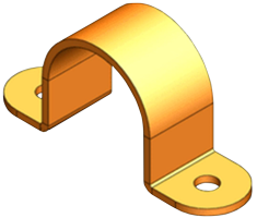
2 Hole U Bracket
Sample Model
This project will allow you to experience two methods to build the same object, using first the first method: a closed 2D profile, and second method using a open profile. Set-up your part file in the Document Settings with ANSI Standard and Units set for Imperial measurements (inch, pound, second).
- Create a model part file and set-up standards, units, folder/file name, then using the web tutorial page
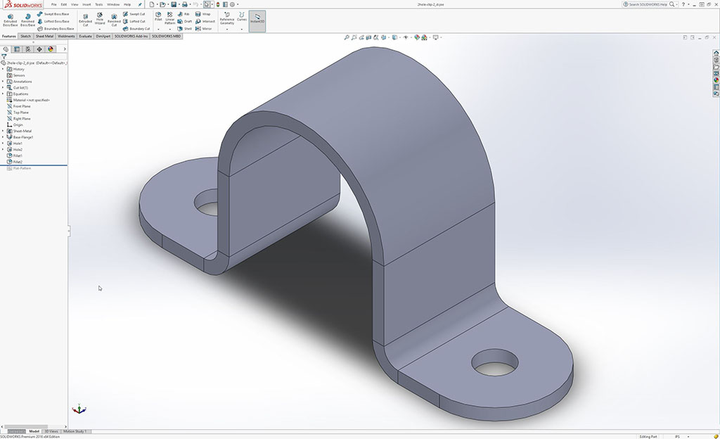
 How to create U bracket sheet metal, and/or a second video tutorial SolidWorks tutorial How to Create U Bracket in Sheet Metal, 9.20 create the steel two hole U bracket with a closed profile sketch (using the imperial dimensions shown in the first tutorial) assigning a steel material, favorite colour for appearance, filling in your summary and custom information, and ensure it is saved in a separate folder with a name similar to: td2-1_d-joe_2hole-clip, with file names:
- Model part name: td2-1_d-joe_2hole-clip_P_closed-profile.sldprt,
- Save As image JPG: td2-1_d-joe_2hole-clip_P_closed-profile.jpg
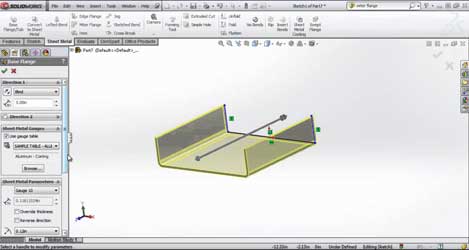
- Create another model part file and set-up standards, units, folder/file name, and now create the same bracket, by making a 2D Sketch with an open profile, then using the sheet metal Base Flange sheet metal feature, 5.07 using 12 gauge steel (steel gauge table) with a bend radius 0.13 inch (override) with a K factor bend allowance of 0.5 and ensure it is saved in same folder similar to: td2-1_d-joe_2hole-clip, with file names:
- Model part name: td2-1_d-joe_2hole-clip_P_open-profile.sldprt,
- Save As image JPG: td2-1_d-joe_2hole-clip_P_open-profile.jpg
- Using our custom template, make a drawing of the open profile model (step 2 model) showing the three ortho views with dimensions, isometric, and the flattened view, and ensure it is saved in same folder similar to: td2-1_d-joe_2hole-clip, with file names:
- Drawing name: td2-1_d-joe_2hole-clip_D_open-profile.slddrw,
- Save As image JPG: td2-1_d-joe_2hole-clip_D_open-profile.jpg
- Hand in whole folder with 6 files for evaluation after you have completed and handed in the Solidworks mod/as/dwg Self/Peer Checklist sheet. Remember you must include 2 differently created model builds, 1 drawing based on model 2 with jpg's (1 folder with 6 files)
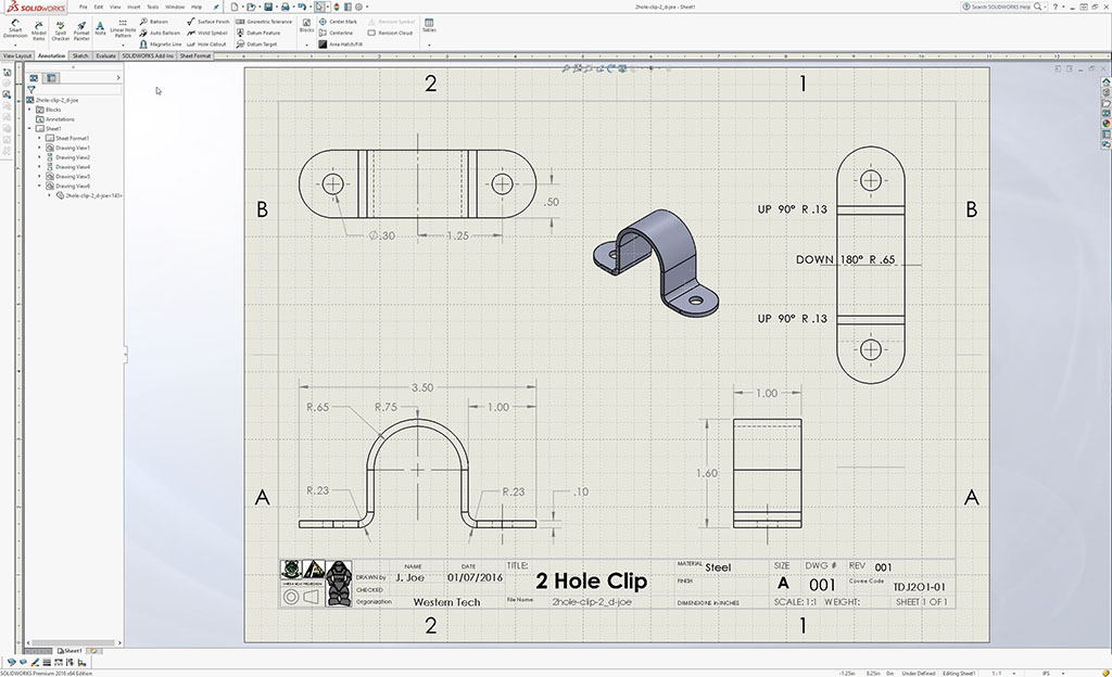
Sample DWG
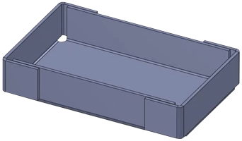
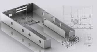
Simple Box Pan
Another simple sheet metal project, this time a box adding more tools to try out this time and building the model two different ways, ![]() using the sheet base flange sketch and, from a solid, 4.34, to understand different build methods.
using the sheet base flange sketch and, from a solid, 4.34, to understand different build methods.
Some of the aluminum 6061 alloy box specs are: 2 * 3", 1/16 thickness, relief circles 0.2", edge flange bends - outside blind of 0.75" with a bend radius of 0.075" and then a 0.15" open butt corner gap with a corner edge flange offset from surface also at 0.75" selecting offset from surface of 0.001" (sample flange settings). Remember to set-up your part file in the Document Settings with ANSI Standard and Units set for Imperial measurements (inch, pound, second).
- Create a model part file and set-up standards, units, folder/file name, then follow the steps in the Sheet Metal Box, 8.48 video (note video shows sheet metal tool bar vs sheet metal tab, same process though), using the specs above, create the same aluminum box and save in it's own folder: td2-1_d-joe_s-box, with file names:
- Model part name: td2-1_d-joe_s-box_P_sheet.sldprt,
- Save As image JPG: td2-1_d-joe_s-box_P_sheet.jpg
- Next, create another model part file and set-up standards, units, folder/file name, and create the same box, this time starting with a solid 3D part to a sheet metal part, 2.55 using the Convert To Sheet Metal tool on the Sheet Metal ribbon with the specs above to end up with the same box and save in the same folder: td2-1_d-joe_s-box, with file names:
- Model part name: td2-1_d-joe_s-box_P_solid.sldprt,
- Exported image JPG: td2-1_d-joe_s-box_P_solid.jpg
- Using our custom template, and create two sheets (copy and paste the tabbed sheet), one for the ortho/dimensions and ISO, and the second sheet for the the flattened pattern/folds and bend table, 3.10 and save in the same folder: td2-1_d-joe_s-box, with file names:
- Drawing name: td2-1_d-joe_s-box_D_solid.slddrw,
- Save As image JPG: td2-1_d-joe_s-box_D_solid-ortho.jpg
- Save As image JPG: td2-1_d-joe_s-box_D_solid-pat.jpg
- Hand in whole folder with 6 files for evaluation after you have completed and handed in the Solidworks mod/as/dwg Self/Peer Checklist sheet. Remember you must include 2 differently created model builds, 1 drawing based on model 2 with jpg's (1 folder with 7 files)
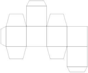
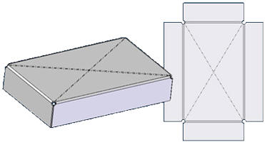
Custom Box Pattern and Build
This project, you will have the opportunity to decide on your own box design and once your custom pattern is printed out in step 4, you will make it out of thin card stock (thick paper) to see if your design actually works. This ![]() video tutorial, 4.33 is a simple overview of what you will be doing.
video tutorial, 4.33 is a simple overview of what you will be doing.
- Review SolidWorks TNT - Design Cardboard Boxes with Sheet Metal Tips-N-Tricks video, note flange position is Material Outside, bend radius 0.001, and K factor to 0, then review SolidWorks Sheetmetal for Packaging example on making a basic box from scratch
- Create your own custom box with lid by either designing from scratch as above or by copying a picture pattern. The only restriction is the flat pattern must fit on a regular letter sized page at 1:1 scale if it were printed, so in other words, relatively small box
- Save all your work in a folder: td2-1_d-joe_cust-box, file named: td2-1_d-joe_cust-box_P.sldprt and td2-1_d-joe_cust-box_P.jpg, then again using our custom template, make a drawing with two sheets showing the three ortho views with dimensions, isometric, and on the second sheet the flattened pattern view and save in the same folder: td2-1_d-joe_s-box, with file names:
- Model part name: td2-1_d-joe_cust-box_P.sldprt,
- Save As image JPG: td2-1_d-joe_cust-box_P.jpg
- Drawing name: td2-1_d-joe_cust-box_D.slddrw
- Save As image JPG: td2-1_d-joe_cust-box_D-ortho.jpg
- Save As image JPG: td2-1_d-joe_cust-box_D-pat.jpg
- Also export a dwg/dxf file with geometry and bends only for print. Using the dwg file, open in Draftsight, add your name on the top centre of the box and print box pattern, cut out box pattern, and put together as a prototype.
- Hand in whole folder with 6 files for evaluation after you have completed and handed in the Solidworks mod/as/dwg Self/Peer Checklist sheet and your paper prototype build. Remember you must include sheet metal model build, 1 drawing with 2 sheets with jpg's, and one exported dwg edited file (1 folder with 6 files).

Advanced challenge here is to download a vector pattern and export to .dxf file to import into SolidWorks and then resize if necessary to fit a standard letter sized page. Sample video showing part of this process called ![]() Folded Box in Sheet Metal, could be very helpful showing how to create a complex box pattern. Outside graphics could also be another option to add after pattern is complete. One place some patterns can be downloaded is from Freepik.
Folded Box in Sheet Metal, could be very helpful showing how to create a complex box pattern. Outside graphics could also be another option to add after pattern is complete. One place some patterns can be downloaded is from Freepik.
Check this quick video if you are curious how you would actually make a sheet metal open pan box with the ![]() proper tools, 1.33,
proper tools, 1.33,
Evaluation:

Ensure that you have included all required files and folders named in the correct naming conventions. Sample naming conventions have been provided above, which you could just copy and change the name. Remember your to dimensioning view placement, spacing, and scale properly.
| Evaluation Breakdown Component Descriptions | Marks |
|---|---|
| Always double check that you have completed all components for full marks. | |
| Simple Bracket - two version model builds, ortho drawing, iso, flat and dimensions | 30 |
| Simple Box - two version model builds, ortho drawing, iso, flat and dimensions | 40 |
| Custom Box - closed box model, ortho drawing, iso, flat and dimensions, prototype | 50 |