Unit 3: Grade 11/12 Technological Design - Robotics - Structure and Materials
This unit will refresh you on Solidworks, cover robot design in more detail with research, FIRST robotics, related materials, measurements, frames, robot joints, and 3D modeling using SolidWorks.
Course Units and Descriptions
Use this table for an overview and navigate to each of the course unit pages.
| Unit | Description |
|---|---|
| Review course outline for more details | |
| 1 | Careers & Safety- Intro, computers, organization, and research career |
| 2 | Engineering Communication- Technical sketching, ortho-ISO, custom ortho, and robot design |
| 3 | Structure and Materials- Materials & measurement, joints, frame, and 3D model |
| 4 | Driven Mechanisms- Gears, gearbox to wheel, drive train, and 1st function |
| 5 | Functions and Integration- Body base, pneumatics, 2nd and 3rd function |
| 6 | Robot Assembly- Robot build, function supports, drawings and presenting |
| 7 | Marketing and Portfolio- Web authoring, portfolio and presentation |

Unit Content Activity Quick Links, Click to Jump to Specific Activity!
- Unit 3, Act. 1: Introduction (Review) to SolidWorks 3D Modeling
- SW Intro, SW Model Links, SW Drawings, File types, Folder & files, SW TroubleShooting,
(Create) Toggle Clamp - Part/DWG Organization, Model Tut - Ass. Info - Ass. Tut - DWG info - DWG tut, Evaluation - Unit 3, Act. 2: Roughing Up a Robot Design
- Where to Start, Support and considerations, Expert Areas, Sketching Ideas, Sample Bot Assembly, Components & Drawings,
(Create) Overview, 1 Expert PPT, 2 SPICE Applied, 3 Sketches, Evaluation - Unit 3, Act. 3: Robot all Framed Up
- Making Robot Frame, SW Tips, Weldments, 2D Profiles, File Naming, Matrix for Frame, Considerations in: Design, Material, and Build
(Create) Matrix for Material, 2D Profile, Frame 2D Sketch, Frame Create, Frame Holes, Frame DWG, Evaluation
 Unit 3, Act. 1: Introduction (Review) to SolidWorks 3D Modeling (SW)
Situation:
Now that students have experienced and gained knowledge and skills on engineering communication, standards, methods, and process, using a "bigger tool box", SolidWorks will allow for more opportunity to design very specific and detailed designs.
Problem/Challenge:
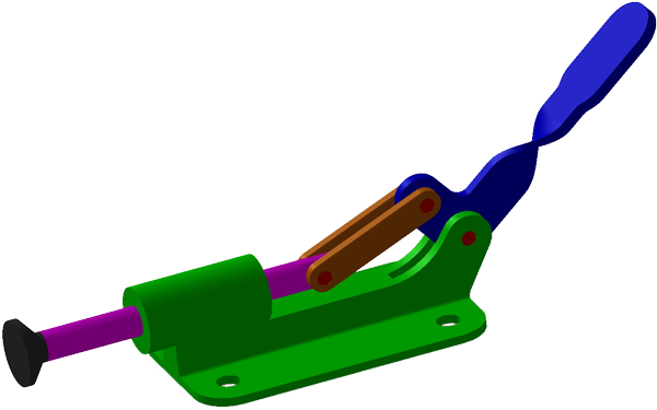
Students are to review and further expand their skill and knowledges using SolidWorks as a tool to help with the engineering design process. Create a toggle clamp assembly in SolidWorks, then create an orthographic drawing sheet set using supplied template drawing file with assembly, exploded with BOM and bubble Id, and all model parts for 8 sheets in one drawing file.
All model parts must be placed based on the three rules for the front view, which should already been taken into account when drawing the initial 2D sketch for the model. Scale, space, and engineering standards for dimensions must be taken into consideration. Overall and detail dimensions must be placed properly with spacing and locations. The shaded ISO will need to be scaled, leaned correctly, and information block filled in correctly, using custom properties, summary information, and notation. Each student will have a custom size for the lengths of the toggle slide, cam, and base times 2, using their number on the alpha list for unique sizing to each student's project.
Once complete a self and peer evaluation checklist will need to be completed and handed-in the same time the digital folder/files are submitted in drop-off.

Investigation/Ideas:

Introduction/Review to SolidWorks
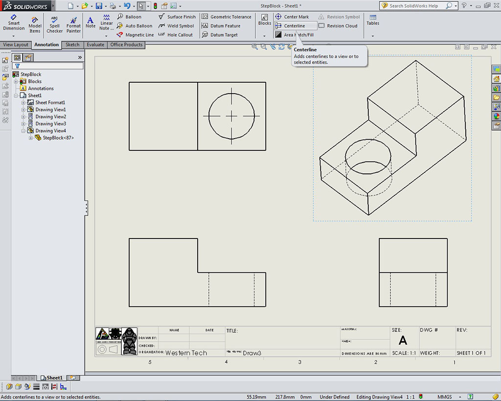
Creating 3D model in SolidWorks with the step block should be straight forward using the steps, pictures, and instructions given. Students should be aware of key information as they go through this step block tutorial such as parametric driven, integrated 3D CAD/CAM/CAE solution, used by discrete manufacturers for mechanical engineering, design and manufacturing. With all of the previous experience with sketching, drawing views, selecting the front view, dimensioning, 2D drawing, and 3D introductory modeling, this should be easy to pick up the basics, as you are already familiar with the previous programs used. The following list are concepts, standards, steps, and terms that you should already be familiar with:
- Folder/file organization, and naming
- SW Program layout, menus, and tabs
- Mouse controls, gestures, and shortcuts
- Drawing Standards (ANSI) and units
- Model part creation
- Planes and Front view Drawings
- Triad and Origin point
- New and editing 2D Sketches
- Center and Construction lines
- Basic lines, Shapes and Trimming
- Detail scrubbing
- Relations and Dimensioning
- Under, Fully, and Over defined
- Feature Tools
- Extruded Boss/base and cut
- Fillet and Chamfers
- Material and Appearances
- Centre line and Mirror
- Bidirectional extrude cuts
- Hole wizard
- Revolved Boss/base
- Adding planes, creating a Loft
- Dynamic Mirror
- Multiple entity extrudes
- Mid plane Extrudes
- Offset Extrudes
- Tape measure
- Part Descriptions

Common Key Terms
- CAD- Computer Aided Designing is a technology concerned with creation, modification and optimization of a design - (SolidWorks, ProE, Catia, etc.)
- CAM- Computer Aided Machining is a technology which involves computer systems that involve, plan and control manufacturing process - (SolidCam, MasterCam, HMS Works, etc.)
- CAE- Computer Aided Engineering helps us to do the analysis of the CAD created product - (Simulation, Ansys, Abaqus, etc.)
- design intent - how your model behaves when dimensions are modified
- parametric - features and relationships of the model, which is intended to capture the product’s behavior
- constraints - component characteristics between two or more entities defining that component and/or property
- relations - is a relation among the specification space and the description space, such that the related CAD-function is preserved
- fully, over, and under defined - does your object drawn have the right amount of information needed by the program
- best practices - are generally good drawing habits to keep organized, create less problems, and ease of work
SolidWorks Model Building Resources
There are several resources on the web that can be helpful when familiarizing yourself with SW, a program of this caliber.

- Comparison of CAD Editors
 Selecting a Workstation
 SW CAD History
- Imperial or Metric ?
- Wikipedia on SW
- SW Main Site
- SW Basic Introduction
- SW Web Help
- 2D Sketch tools
- 3D Feature tools
- SW Tutorials
- SW tutor outline
- SW Catalog of Lessons (req log-in)
 SW in 10 Minutes, 13.5
- SW machine design, 5.27
- SW overview all in one, 5.07
- Guide to SW 2014
- Sketch Relations 1 (11.54)
- Sketch Relations 2 (13.59)
- Quick fully define tips
- 100 SW Basic Tut. play list
- SW Tips (22 min)
- 30 SW Tips (22.10)
- 10 Golden Rules
- 3D Modeling Best Practices
- Part Modeling Best Practices
- SW Tips for Beginners
- Text in SW Tutorial
- SW 3D Text Path (3.5)
- Tips with Text in SW
- Basic Best Practices
- Resilient Modeling
- Best Practices (22.10)
- Design Like a SW Wizard
- Design Blog
- SolidWorks 2014 Blog
- 186 SW tutorial play list
- 46 TEDCF Tutorials 1
- 32 TEDCF Tutorials 2
- Tips & Tricks 2014 (32.56)
Assembly Resources
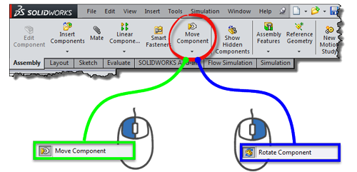
Assemblies are simply a number of parts or further sub-assemblies put together using mates. Sub-assemblies can be used to organize your components of your product design. There are many different mate types depending on how you want parts to interact or connect to other parts or components. It is a standard practice to place your first part in the assembly as your main or base of your assembly set to assembly origin, then bring your other parts in mating to the first part. Use the left mouse to move and the right mouse button to rotate your parts as you place your parts in your assembly. The following resource links can be helpful for you to start creating assemblies through correct mating practices.
- SW mate help
- The Fix/Float tool, 1.45
- Intro to Mates, 10.35 min
- Best mating practice tips 1-4 index
- Advanced Assembly Mates, 4.5 min
- Limit Mates, 11.27 min
- Collision Detection, 3 min
- Exploded View in assemblies
- Exploded Views In Assemblies, 4.42 min
Solidworks Drawing Files
The basics of making drawings are similar in most CAD programs, the model file is used as a source for information to draw the views in drawing file. If something is changed in the model file the drawing will up date and if changes are made in the drawing, the model will also be updated (Parametric) with the new changes.
Model Drawing Resources
- Getting Started in DWG
- Drawings
- Assembly & Part DWG
- DWG Environment, 5.19
- Saved Views
- Drawing and Detailing
- Section Views, 8.11
- Detail Views, 2.23
- Inserting Model Dim, (4.08)
- Exploded Views
- Exploded view & BOM, 9.28
- Sheet Format vs DWG Sheet, (3.10)

SolidWorks File Types
There are several file formats that your work can be saved in. Your model work in SolidWorks has it's own proprietary or native extension unique to its part files. Here are examples of some of the most common file formats and naming conventions you commonly used:
- SLDPRT - SolidWorks model part: td2-1_d-joe_2d-step-block_60x30x30.sldprt
- EPRT - Epart file allows users to view with a free e-drawings application: td2-1_d-joe_2d-step-block_60x30x30.eprt
- STL - Common CAD standard STereoLithography for use with Cura to convert file to print 3D: td2-1_d-joe_2d-step-block_60x30x30.stl
- JPG - Joint Photographic Experts Group: td2-1_d-joe_2d-step-block_60x30x30_dwg.jpg (note -dwg or -d, as to not overwrite your model jpg that was possibly saved file earlier )
- PDF - standard Portable File Document: td2-1_d-joe_2d-step-block_60x30x30_d.pdf (note -dwg or -d, as to not overwrite your model PDF that was possibly saved earlier)
Drawing Resources
Proper Folder and CAD File Use
When a model part is saved and drawing and/or assembly files are created, they reference/use the information from the model file, i.e. they are linked together. It is recommended to save these your CAD files in the same folder, keep file names simple, short, and descriptive for organization and simplicity. If files are renamed after CAD work is done, such as deciding to rename your model file which a drawing and assembly are dependent on, then the drawing and assembly file will no longer work. More details here: folders, files, organization, and naming convention which we will look at more closely in the future.
SolidWorks TroubleShooting
Below are some current know issues on our computers that may be affecting your use with SolidWorks:
Open GL Graphics setting, adjusting graphic settings for performance, if SW is slow/lagging
- Ensure you do not have any documents open when accessing System Options | Performance settings
- Ensure the option "Enhanced graphics performance (requires SOLIDWORKS restart)" is unchecked. If checked, uncheck, restart and go back into options, then the OpenGL option should now be available to try
View Transparency after sketch edit - Temporary fix
- You can (temporarily) fix hidden lines showing in the shaded view by going into the DisplayManager and clicking on the material, then clicking off of it. It will break again after entering and exiting a sketch.
Create/Construct:
Toggle Clamp Info
Create a toggle clamp following the steps and support pictures below. Focus on following the steps, keeping in mind the underlining concepts of selecting the front view, 2D sketching, 3D modeling, dimensioning standards, with respect to Engineering standards and communications of ideas. Major tools/process used to create the part models used in this tutorial include:
- Folder/file organization, and naming
- SW Program layout, menus, and tabs
- Mouse controls, gestures, and shortcuts
- Drawing Standards (ANSI) and units
- Model part creation
- Planes and front view drawings
- Triad and Origin point
- New and editing 2D Sketches
- Center and Construction lines
- Basic lines, shapes and Trimming
- line arc scrubbing
- Relations and Dimensioning
- Under, Fully, and Over defined
- Feature tools
- Extruded Boss/base and cut
- Fillet and Chamfers
- Material and Appearances
- Centre line and Mirror
- Bidirectional extrude cuts
- Hole wizard
- Revolved Boss/base
- Adding planes, creating a Loft
- Dynamic Mirror
- Multiple entity extrudes
- Mid plane Extrudes
- Offset Extrudes
- Tape measure
- Part Descriptions
Part/DWG Organization
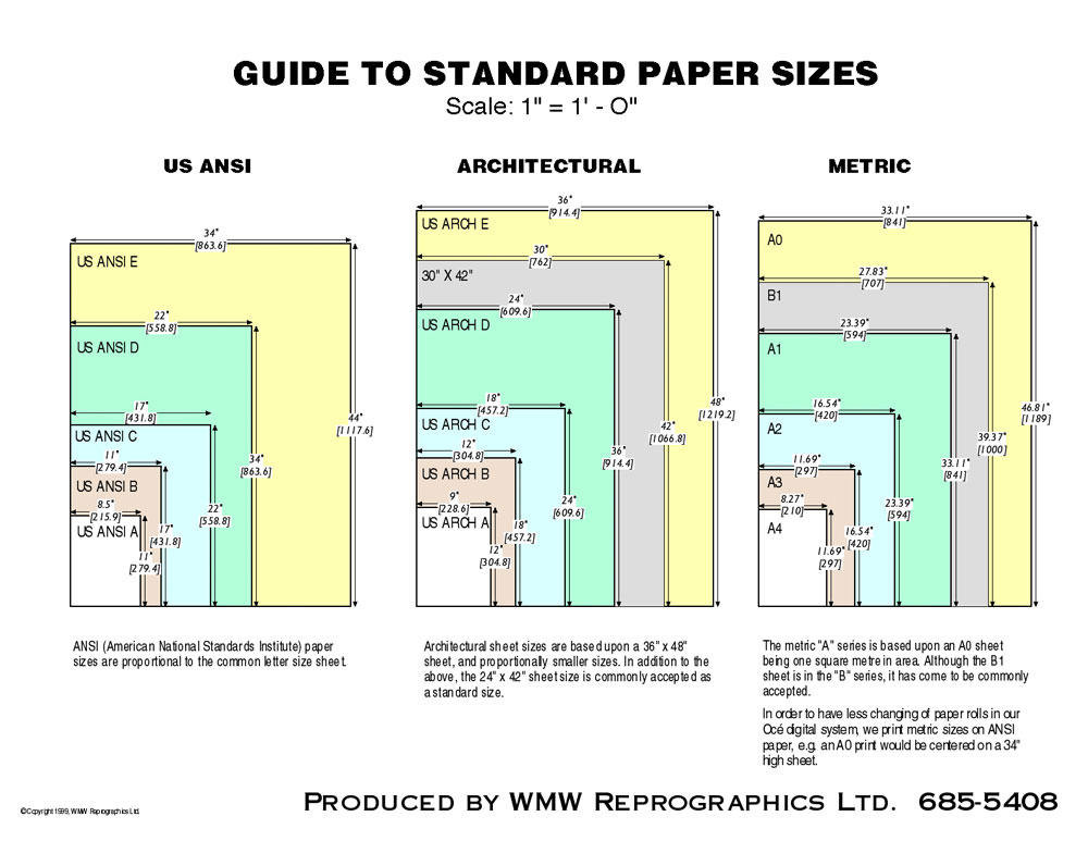
Sheet Size
Std's
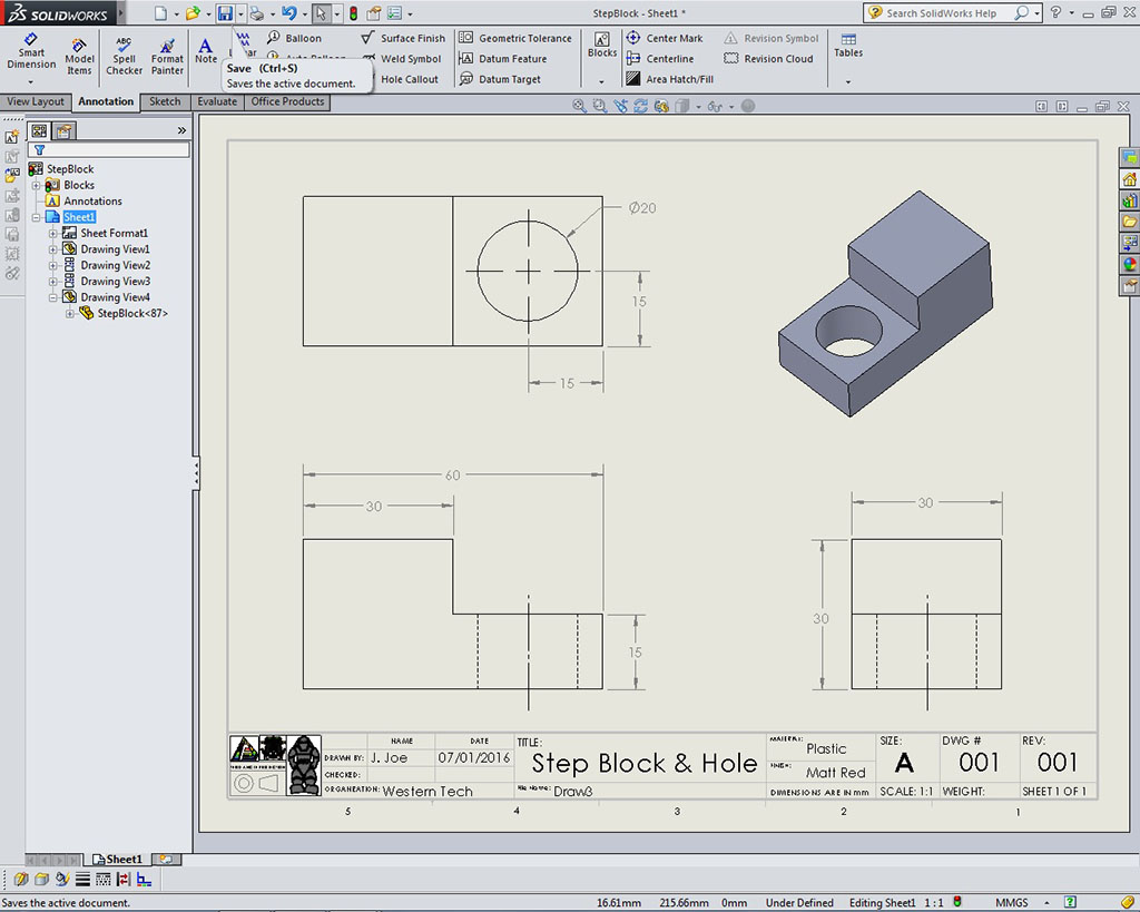
Thinking ahead, making up templates for your work will make your work easier, faster, and more professional. Below is an example of a drawing information block that has been populated automatically (easy way to link properties to a SW dwg) from information in the model part using auto-fill fields. This is done by inputing the information in the part model file, then creating the drawing file with linked fields. For your benefit, a template has been created similar to the one below showing just the information block on a A standard sized sheet, which is the same size you use to write your notes on daily (8.5" x 11").

Each student will have a custom size for the lengths of the toggle slide, cam, and base times 2, using their number on the alpha list for unique sizing to each student's project. Ensure your front view that is drawn is in-fact the correct front view based on the three rules. Remember folder/file use and naming convention, name features in feature tree, add the material, appearance, summary information, and custom properties for each custom part made. The properties you fill in for your model will keep record of, organize, and auto-fill DWG template fields.
Materials

Appearances
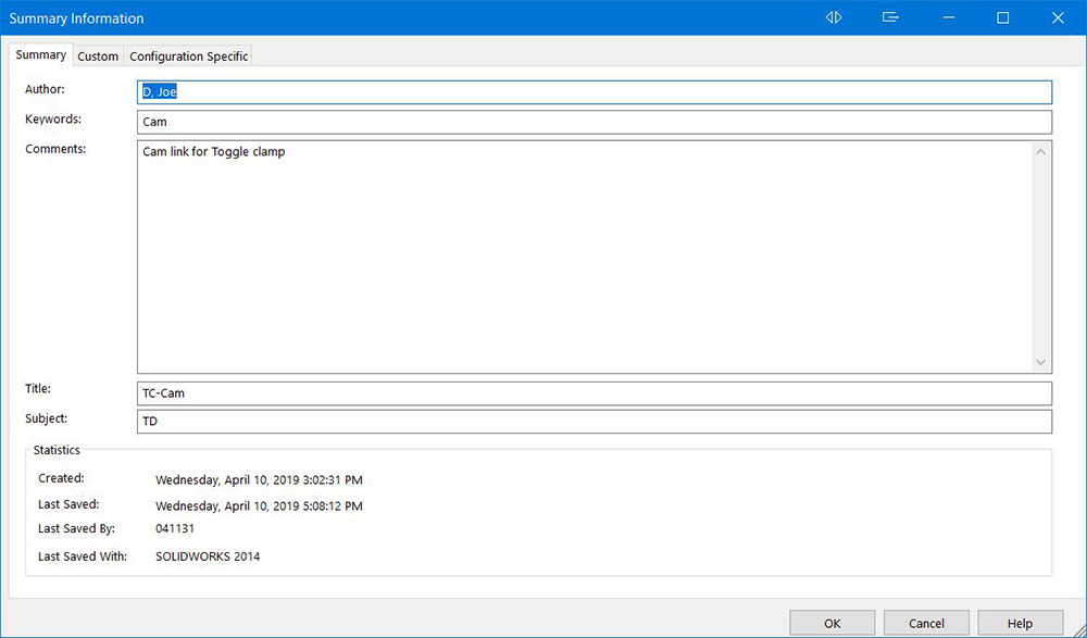
Summary
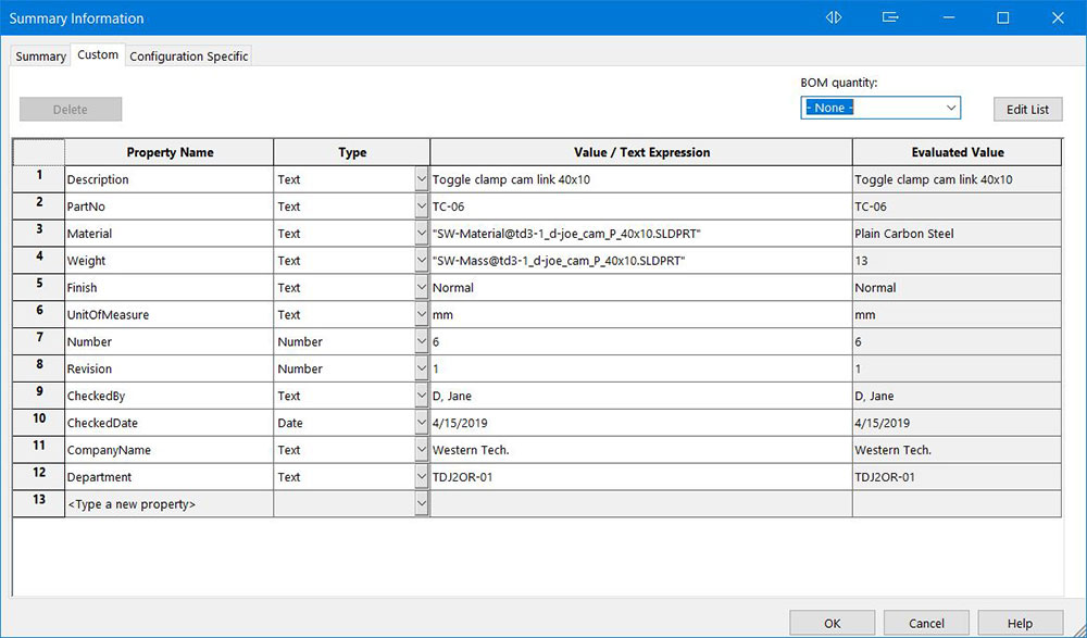
Custom
![]() Ensure you have a folder, example folder name: td3-1_d-joe_toggle-clamp inside your class folder on your USB flash drive so that you can save all related model files together for ease of use, organization, and for handing into the drop-off folder later. For files use appropriate file naming convention, example: td3-01_d-joe-tc-pin.sldprt
Ensure you have a folder, example folder name: td3-1_d-joe_toggle-clamp inside your class folder on your USB flash drive so that you can save all related model files together for ease of use, organization, and for handing into the drop-off folder later. For files use appropriate file naming convention, example: td3-01_d-joe-tc-pin.sldprt
Toggle Clamp Part Models Tutorial Steps
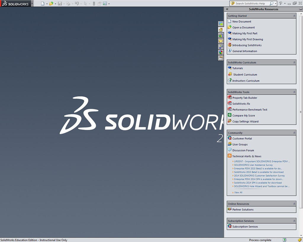
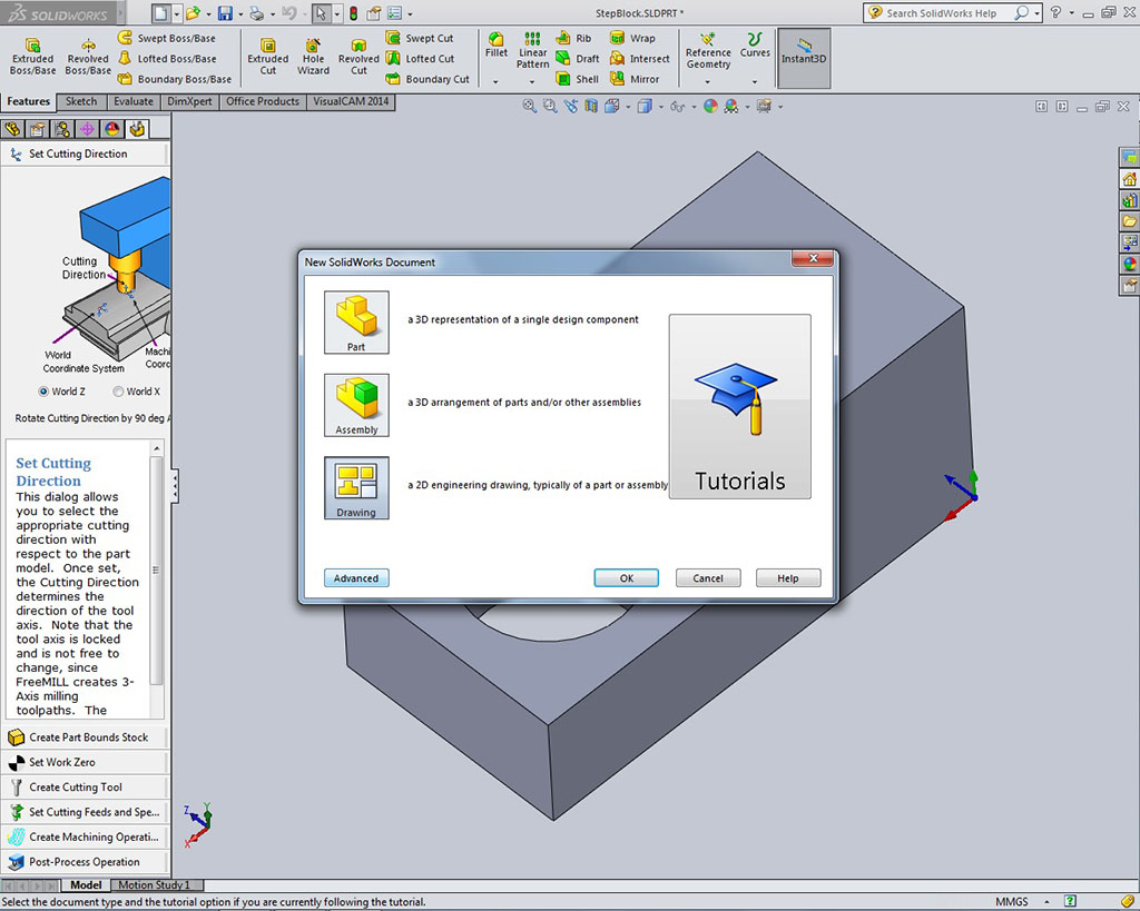
- Start-up: Run SolidWorks application, and you will get an opening screen
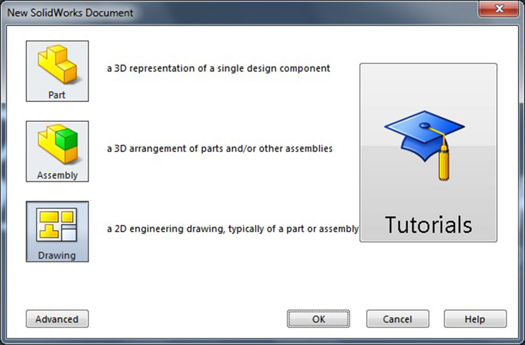
- New Part: Select new model part (in step 3, you will want to save it as a template file once file is set-up, by creating a CAD>SolidWorks>Custom>My-templates folder structure and have SW in the options, systems, file locations updated, so you don't have to do step 3 every time)
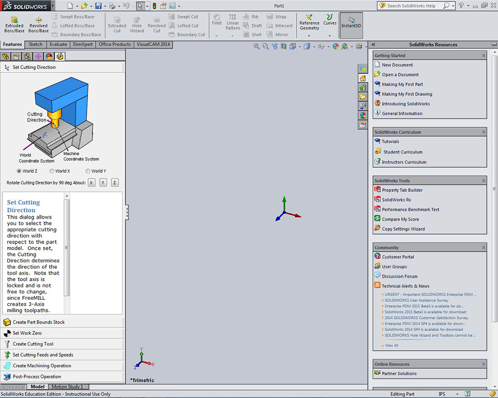
- Model Workspace: Ensure you have ANSI standards and millimeters by selecting Options at the top, selecting Document Properties, and ANSI is selected as the drafting standard, then select Units and check that your document is in millimeters (also for all of your parts for this project). Turn your grid on in the grid section and any other elements you think will help with the base template you will use over and over. Select the Sketch tab at the top to bring you into sketch mode and select your 2D sketching tool, in this case the line tool, Select the plane you want to sketch on, keeping in mind the part you will be modeling will be infarct be the correct front drawing view. Once selected, the other two planes should disappear
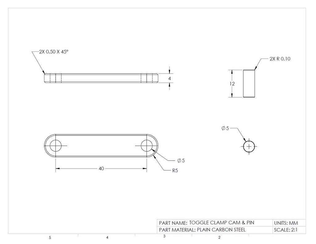
- Pin/Cam DWG: Review the drawing showing the dimensions for both the toggle pin and toggle cam (note all DWG's show here in this project are not necessarily great examples, but do have enough information to build the parts for the Toggle Clamp)
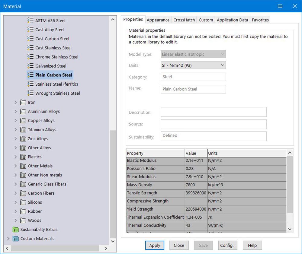
- Toggle Pin: Start with a new part file and create the toggle pin 2D sketch using the circle tool on the front plane, dimension to fully define, extrude to length, change material to carbon steel, add an appearance colour, and save. Always get into the habit to save with appropriate folder/file use and naming convention, name features in feature tree, add the material, appearance, summary information, and custom properties for each custom part made and save in a optimum isometric view for all your parts, save again as your first part, then delete the part and then save the blank file (with all of the data, settings, and standards) as a template file in your recently created template folder
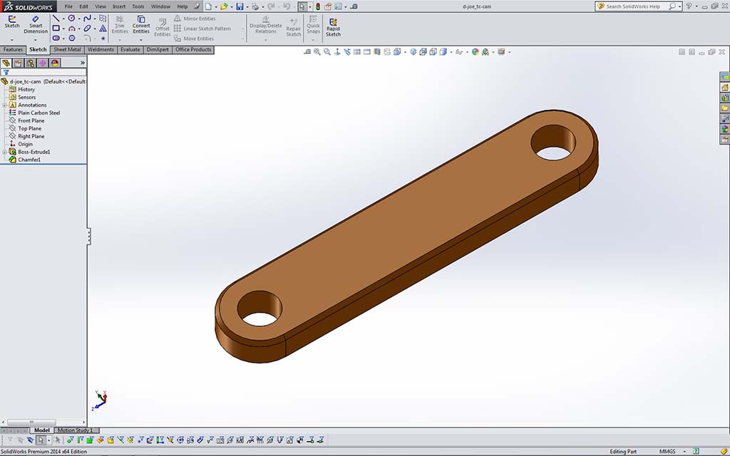
- Toggle Cam Create the toggle cam 2D sketch using your recentl template, ensuring correct front view, using rectangle shape and two circles, then cut the pin holes, chamfer the edges, update the material to carbon steel, add appearance colour, and save. Remember to use your custom alpha number times 2 from student list (PPT order #) for the lengths of the toggle slide, cam, and base times 2, for unique sizing to each student's project. Again... always get into the habit to save with appropriate folder/file use and naming convention, name features in feature tree, add the material, appearance, summary information, and custom properties for each custom part made, and save in a optimum isometric view for all your parts
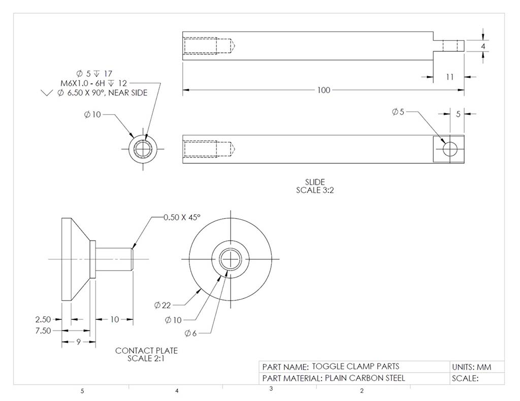
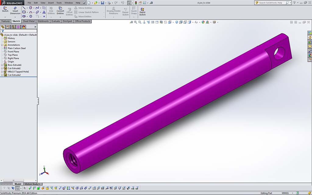
- Slide/Plate DWG: Review both the toggle slide and contact plate dimensions. Note the slide has a straight tapped hole with a near side countersink and a 2 step end blind condition that you will need to create using the hole wizard tool
- Toggle Slide: Start with your 2D sketch with your circle tool on the right plane, then extrude, remove material to create the slot, cut pin hole out, then on the contact plate side use the hole tool to create your M6*1 mm pitch tapped threaded hole 17 mm deep with threads going 12 mm deep and a counter sink of 6.5 diameter at 90 degrees. Turn on cosmetic threads on in the options, document properties, under detailing, and select cosmetic thread to show representation of the threads. Remember to update material to carbon steel, add colour appearance, update custom properties, and summary
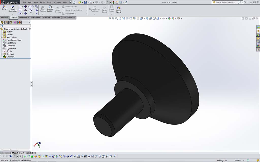
- Toggle Contact Plate: Use a centre line and draw half of your design, dimension, use the Revolve Extrude, update material to carbon steel, add an appearance colour, update custom properties, and summary
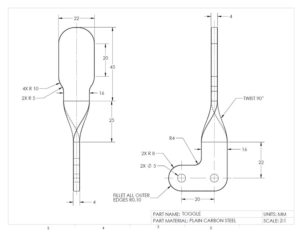
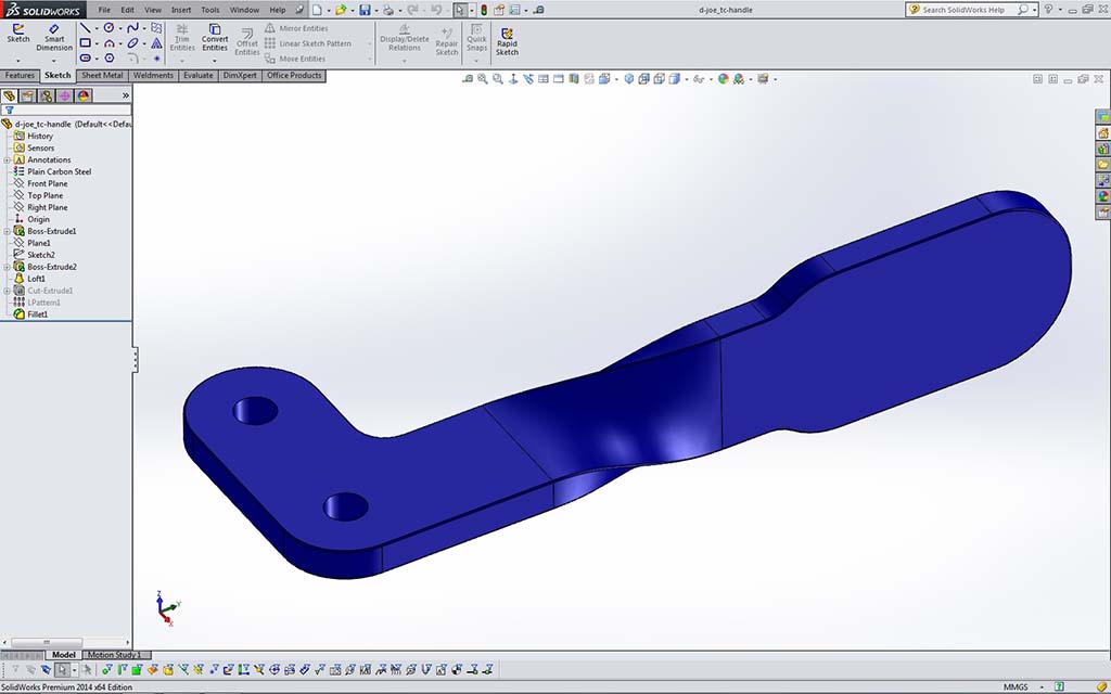
- Toggle Handle DWG: Review the toggle handle drawing and note there are three sections: the pin base, loft twist, and the rounded handle
- Toggle Handle: New model file, start with the two pin holes on a 2D drawing and create the base/elbow of the handle, Extrude Mid Plane, then sketch on bottom of twist with Convert Entities, then Reference Geometry to offset a plane distance of twist, create second profile of twist to use the loft tool to create the twist to the handle, then create the 90 flat handle using dynamic mirror, lines, and arcs, with all arcs tangent. Remember to update material to carbon steel, add colour appearance, update custom properties, and summary
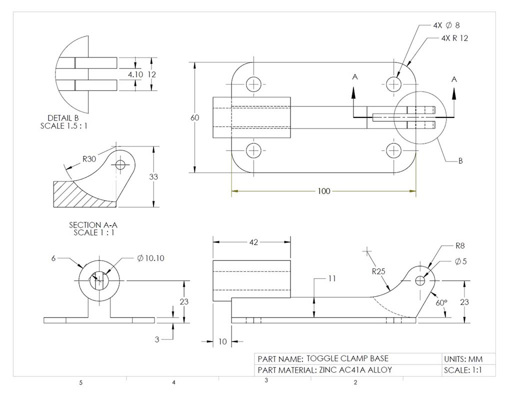
- Toggle Base DWG: Review the drawing information on the toggle base and note three main sections, the base, mid section, and slide support
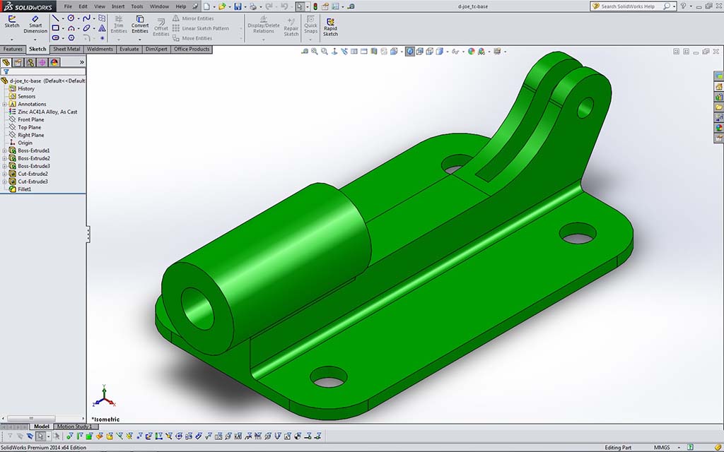
- Toggle Base: Create new model file and ensure that you have a plane going through centre of mid section. Start with support base with rectangle tool, add outside rounds, then your 4 mounting holes, extrude, then work on your centre middle piece 2D sketch (note there is a straight line segment between the R25 and R8 top inside curve that is parallel to the 60 degree line on the back and both curves are tangent to the straight line), extrude mid plane, remove cut for toggle handle base using circle tool and cut out slot using mid plane again, then create the round slide support using the circle tool on the end of the centre middle piece and offset extrude. Include 2 mm fillets on slide cylinder support and bottom of horizontal support on plate. Update material to Zinc AC41A Allowy, as cast, add colour appearance, update custom properties, and summary
- Toggle Clamp Parts Review: Open all of the parts and ensure you have completed them properly. As you review each part, update if needed, the name features in feature tree, material, appearance, summary information, and custom properties for each custom part made and ensure appropriate folder/file use and naming convention has been used. Remember use your custom alpha number from student list for the lengths of the toggle slide, cam, and base times 2, using their number on the alpha list for unique sizing to each student's project. Ensure that each part has been saved with the best ISO view and save the part document (.SLDPRT) and a picture file format (...-p.JPG) adding -p for a unique part file image name as to not overwrite any other jpg image files you will be making
Step 1
Start-up
Step 2
New Part
Step 3
Model Workspace
Step 4
Pin/Cam DWG

Step 5
Toggle Pin
Step 6
Toggle Cam
Step 7
Slide/Plate DWG
Step 8
Toggle Slide
Step 9
Toggle Cont. Plate
Step 10
Toggle Handle DWG
Step 11
Toggle Handle
Step 12
Toggle Base DWG
Step 13
Toggle Base
Toggle Clamp Assembly Info
Making assemblies deals with a whole new file format, accessible in the open or new file window. With all parts in a related named folder with files also named in with file naming conventions learned, you are ready to start the assembly of those parts.

After this point, renaming your part files will cause breaks in your file references back to your model in your assembly and you will not be able to regenerate your assembly for the reasons explained in the appropriate folder/file use and naming convention section.
Major tools/process used to create the assembly model used in this tutorial include:
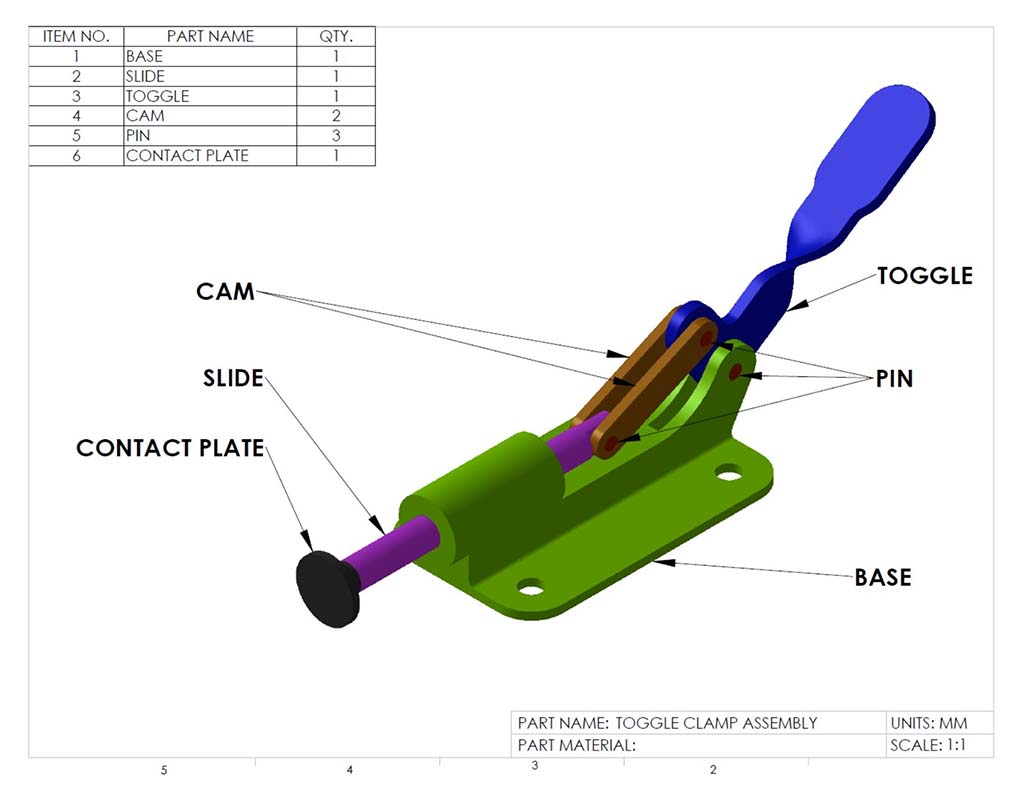
Parts
Assembly
- New assemblies and set-up - naming, location, and design intent
- File child/parent dependencies - file references and control
- Placing first fixed component - lock on origin for both part and assembly (float vs fixed)
- Moving, rotating components - move-left, rotate-right mouse buttons
- Mating parts process - common and advanced mates
- Collision detection - to find out specs on parts colliding for later advanced distance mates
- Mating angles - to limit movement (save in common position prior to bringing into another parent assembly)
If you are using ![]() OnShape (virtual students), you will need to focus on fixing your main part, using the fasten, revolute (with limits for handle) and slider mate tools. Here are some assembley support videos:
OnShape (virtual students), you will need to focus on fixing your main part, using the fasten, revolute (with limits for handle) and slider mate tools. Here are some assembley support videos:
- Building your first assembly in Onshape, 3.49
- Creating Mates (Toggle Clamp), 12.40
- Exploded Views, BOM, and ballon id's, 8.22
Toggle Clamp Assembly Model Tutorial Steps
- You have one or two options when using the provided template. You could use the pick-up template folder location, if you copy the file location using your systems file browser to add another template folder location, but this will only be accessible at school. You could also copy the template file from the school pick-up folder and put into a folder on your USB or your desktop (remember your desktop could be reset, i.e. not the safest location)
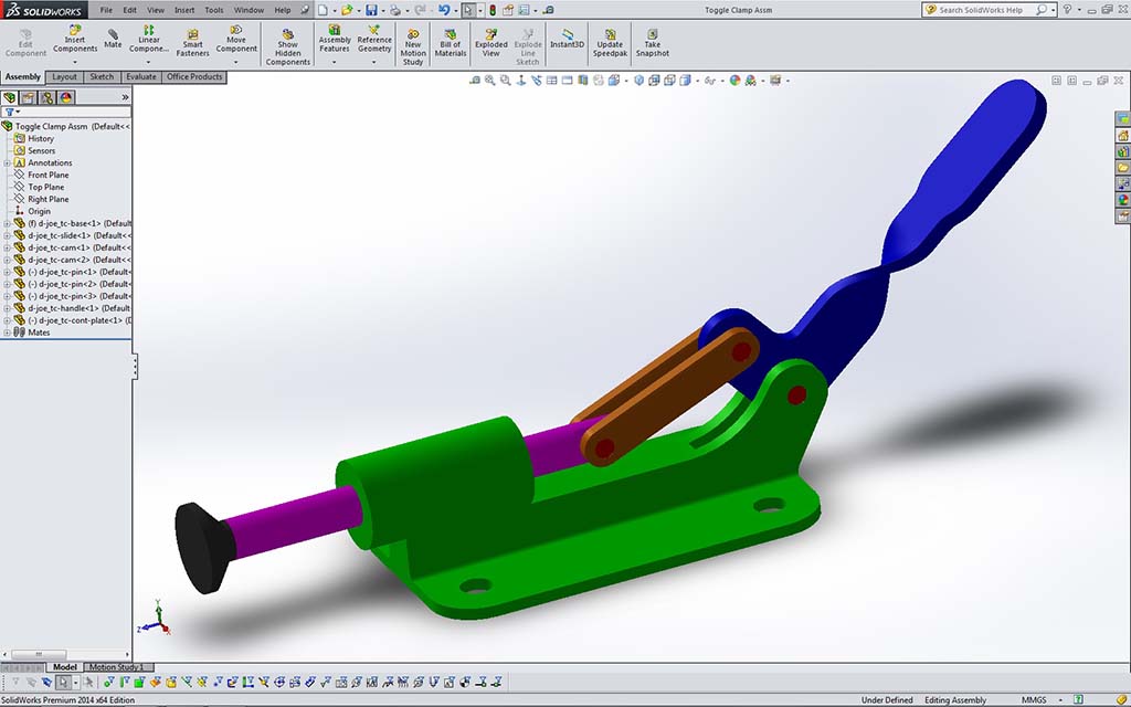
- New Assembly: Create a new assembly from the toggle clamp base part ensuring the part and assembly model origin's line up by accepting original placement without clicking in the drawing space (by default SW will match and place both part origin and assembly origins) resulting in a fixed starting base part both locked on their origins - sometimes it may be necessary to float fixed first part and align in assembly a more appropriate view, just ensure it is placed with front view of your finished assembly in mind and ensure that it is aligned to assembly planes for proper dimensioning later - hint: After placing, go into feature tree and right click to float(un-fix) your part, then use the mate tool to mate the appropriate planes so that you end up with a proper front view - for assembly view command and your drawing placement later... once done, don't forget to change your part back to a fixed position
- Update custom properties and summary for the assembly so it will be ready to use with BOM, DWG, specs, etc. The material is changed to text input instead of an auto field and put "see BOM" (Bill of Materials) or in this case if it is all the same material, just put the material (with multiple part assemblies, it is common that materials may be different for your model parts)
- Insert Component: Place your other parts into the drawing, locating them near their appropriate location and direction which may require you to further move and rotate for easy mating in next step
- Part Mating: Start by mating one part to the original fixed base part using appropriate number of mates to lock part in place
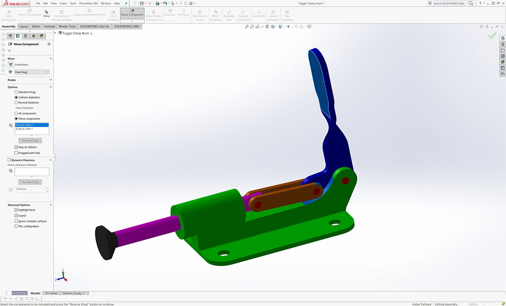
- Advanced Angle Mate: The toggle handle is to have an advanced angle motion with a minimum and maximum travel range using the collision detection feature in the Move Component tool and then modifying advanced part of that
 related mate in this case the angle mate - advanced - Detailed steps below:
 - Using Move Component collision detection (see pictures below for settings)- between the base and the cam collision points by moving the toggle handle to get maximum slide distance (handle should stop and highlight at collision point)
- Exit out with green check mark, select the evaluation tab and select the tape measure, and more the angle between the top of base and front flat of toggle handle to get the minimum angle limit, you should get about 85 degrees, note and continue to next step
- Repeat step 1 and 2 for the slide minimum distance with collision with cams and toggle base (close-up) for toggle handle all the way back, to get the maximum limit angle using the same features selected between the top of base and front flat of the toggle handle, you should get about 158 degrees (shortest distance between two points selected), note and continue to next step
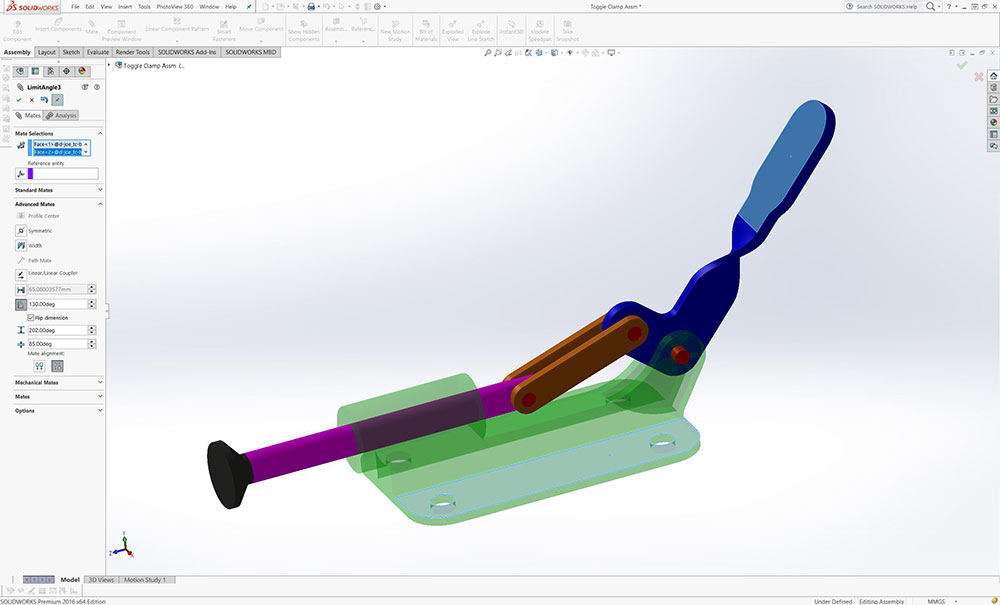
- Select the top of base and front flat of toggle handle, then select angle - you may have to ensure Flip is checked, and the Anti-Angle is selected
- Select advanced mates, and below you will see; Angle, Max Angle, and Min Angle -- Input Angle around 130 for normal view -- Max Angle - set at 202 (180-158=22, therefore 180+22=202), -- then finish putting your Minimum Angle at 85
- Green check mark twice to apply and confirm, then check your rotation by dragging toggle handle
- Exploded View: Create an exploded view using the configurations feature tree tab to create an alternate view, then use the exploded tools to pull your assembly apart showing break-apart view of all model parts used
- File Types: There are several file types available for export, but you will save in two formats, its proprietary file format: SolidWorks Assembly (.SLDASM) and a picture file format (...-a.JPG) adding -a for a unique assembly file image name as to not overwrite any other jpg image files you will be making
Step 1
Max. slide

Step 2
Measure max.

Step 3
Measure min.

Step 4
Angle Mate
Step 5
Advanced
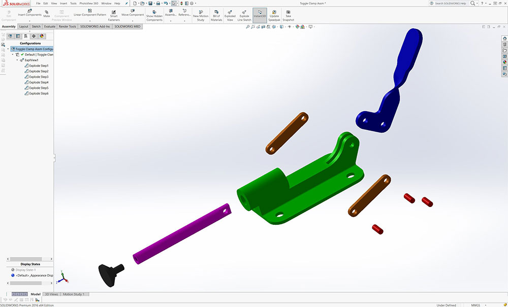
Exploded view
Toggle Clamp Drawings
Above in the Investigation section you will find steps to create a basic drawing using SolidWorks with a simple object called the Step Block. Using the same process with the in-class tutorial steps you will learn about:
Step Block Drawing Process From Grd10
Step 1
New Drawing
Step 5
Views Placed
Step 13
Info Block
- New drawings
- Sheet sizes, scale, and format
- Templates location and use
- Multiple sheet insertion/naming
- Grid setup and use
- Inserting assemblies, parts, and views
- Inserting multiple views
- View pallet
- Projected views
- View configurations and options
- Centre Mark and Lines
- Annotations, dimensions, notes
- Bill of Material table (BOM)
- Balloon identification
- Information block
Using Templates
Sheet Size
Standards
SolidWorks generic drawing templates can be bulky and use a lot of unnecessary space and information specifically on smaller standard sheet formats. Using the supplied A sided custom template file that fits a standard letter sized sheet in landscape format is convenient and practical which has been provided (shown below with all auto fields filled in for the sample TC-Cam part, with only the sheet scale left to enter) in the pick-up folder of the school's network.
Remember, you have one or two options when using the provided template. You could use the pick-up template folder location, if you copy the file location using ![]() your systems file browser to add another template folder location, but this will only be accessible at school. You could also copy the template file from the school pick-up folder and put into a folder on your USB or your desktop (remember your desktop could be reset, i.e. not the safest location) under SolidWorks/Custom/My-Templates folder and ensure under options in file locations, this location for custom templates address is confirmed. For adding multiple sheets with the same template, just left click on your first template and copy and paste to a new sheet as many times as you need.
your systems file browser to add another template folder location, but this will only be accessible at school. You could also copy the template file from the school pick-up folder and put into a folder on your USB or your desktop (remember your desktop could be reset, i.e. not the safest location) under SolidWorks/Custom/My-Templates folder and ensure under options in file locations, this location for custom templates address is confirmed. For adding multiple sheets with the same template, just left click on your first template and copy and paste to a new sheet as many times as you need.
Toggle Clamp Drawing Tutorial Steps
Remember that you ultimately need to make the final decision on where and how dimensions are placed base on the engineering drawing dimension placement. Using the template provided will help with our small A size format and updates several settings in the background such as using ANSI standard, dimension sizes, spacing, etc., but may need to be modified to suite certain situations. Use the steps/key points below to complete your drawings properly:
- New Drawing/Template: Open a new drawing window, select advance at the bottom to get access to custom templates and use provided A-land-mf-cust-prop.drwdot in our school pick-up folder (should already be linked in system option under file pathways)
- Grid: Turn the grid on by going into the Feature Tree, right click on sheet 1 and select Display Grid, (already preset in document settings to 10 mm spacing to help with placement, view spacing, dimensions, etc.
- Sheet copies: Copy the sheet several times by selecting the tab to create multiple sheets in one drawing file (8 required) for all of your parts and assembly, with your assembly being first, your exploded view next, then the next significant part, etc. You will need to edit your "number" in your model parts to match your drawing numbers on your sheets - number according to the part significance in drawing set, ex: main assembly 1, base 2, etc.
- Your first DWG sheet, browse or select appropriate part/assembly (in this case your assembly), Using Multi Views panel (left panel), check off Create multiple views to bring in all three views at once, or select Model Insert for more options when bringing in views. If you have the part open, you will also have the option to bring in your current view of your model (remember, your current view is your best ISO) Select front view and use Drawing View panel to make modifications to set appropriate view style, scale, type, etc.
- Assembly drawing details: show overall dimensions and any other important dimensions necessary for the whole view, bring in a second assembly with an exploded view with the addition of bubble ID for the parts and a BOM "all" template and edit as shown in class demo - changing column info for part number (double click table header - select custom property), delete empty columns, change text size to 9 font, resize table - shrink using top right corner, move using top left corner, etc.
- View Scaling: Adjust sheet scale in the sheet properties for whole sheet to fit your ortho views large as possible appropriate dimensioning space and show in your drawing info block. For your ISO view scale, adjust appropriately - will most likely will be smaller than your ortho views/sheet scale, and show your custom scale by right clicking on ISO view, and select Add View Label, to get custom scale, and then move to appropriate location close to that ISO
- Centre Marks and Lines: Select Annotation tab to get access to the centre mark and line tools to add centre marks and lines to the appropriate views. Customize centre marks (by selecting and modifying left panel settings from sheet to custom sizing) if they are not fitting properly in your current view (in cases of extra scaling in sheet)
- Dimensioning: Using menu Insert >Model Items, will pull in dimensions from sketch and features (Black colour auto vs grey for manually created), then straighten out keeping in mind overall, detail dimension standards, (SHIFT can move dimensions from one view to the other while CTRL will copy), and hole call outs. For manual adding of dimensions (gray colour), the Smart Dimension tool will accommodated most needs. Remember always place dimensions in the view that best shows the feature/detail the most
- Hole call-outs: For complex holes done by the Hole Wizard such as threads, right click on sheet, select annotations, hole call out, then select the circular hole feature to place the fully defined hole call-out detail dimension
- Dimension clean-up: marquee select all dimensions you want to clean up, then move the mouse over the Dimension Palette rollover button to show dimension pallet, then click on the Auto Arrange Dimensions (lower left corner), then fix as necessary
- Information Block: In the Annotation tab , select the Note button to fill in any additional information and/or notes. Remember your part properties will auto fill the information block fields for the parts brought in to that sheet, so make changes in the model custom fields
- File Types: There are several file types available, but you will save in two formats, its proprietary file format: SolidWorks Drawing (.SLDDRW) and a picture file format (...-d.JPG) adding -d for a unique drawing file image name as to not overwrite any other jpg image files you will be making
Points for Placing Most Parts:
Your single drawing file requires one sheet per model part including front pages showing the assembly with major dimensions, second showing exploded view with bill of materials and balloon part identification (8 sheets total). All tabbed pages to be named appropriately with all information blocks filled in. Your multiple drawing sheet file is to be saved in the SolidWorks proprietary native drawing file (.SLDDRW) and a picture file format (.JPG) with the appropriate folder and file naming conventions.
Evaluation:
Make sure your folders, files, organization, and naming conventions are saved correctly, files open up to appropriate views (for example model part and/or assembly - full screen with best ISO view), all CAD files working (double check if you change file/folder names after creating your drawing and assembly files), and include full page JPG images of all CAD work . Remember when you hand in your Solidworks project, make sure you have completed and handed in the SolidWorks Self/Peer Checklist sheet at the same time. This self/peer evaluation sheet (worth 10% of project mark) is there to help you hand in the best product and get written feedback on your completed work before you submit, so that you can improve your work submitted (peer collaboration).

| Evaluation Breakdown Component Descriptions | Marks |
|---|---|
| Always double check that you have completed all components for full marks. | |
| Toggle Clamp: models, assembly, DWG's, and Eval. sheet | 50 |
Unit 3, Act. 2: Roughing Up a Robot Design

Situation:
Students have covered all the Technological Design basics including sketching, design process and application, basic 2D and 3D CAD, and have their PMT package as a resource. More application of these hands-on tasks and processes will help with further learning with the design process, engineering communications and standards, CAD and related tools. Students have the great opportunity to use a sample robot design, it's process, and eDrawing files to practice and build their own using Solidworks. By going through this process, students can use the experience and learning to apply to other problem/challenges.
Problem/Challenge:
You will work as an individual, in small groups, and as a class to familiarize yourself with the 2015 FIRST robotics competition. Decide on a unique expertise area you will represent with over flow people to partner up collaborate and expand (priority given to mechanisms, mechanical, drive system, and CAD) with peers to present their area and how it relates to the game. The pick-up/drop-off folders will be used to share presentations, resources, ideas, and design process in the form of text, charts, photos, illustrations, renderings, CAD drawings, etc..
Students will apply the SPICE design process to this project showing their depth of understanding and their opinion on their priority of functions for their robot design based on the 2015 FIRST competition game. Students will use the PMT pkg, as a resource to support their work with their project design and also continue to use the daily design log to identify and report steps/tasks taken and new learning.
For your robot design, you will research, collaborate, generate ideas, and have discussions with your peers/partners to decide on what priorities your robot should have, so that you can establish what your robot functions will be. With those priority functions, you will create some preliminary sketches of three different robot designs in isometric format, one final ISO refined design with function details, notes, and labels, and one ortho showing relative size, function locations, and major dimensions.
Investigation/Ideas:
Where to Start?
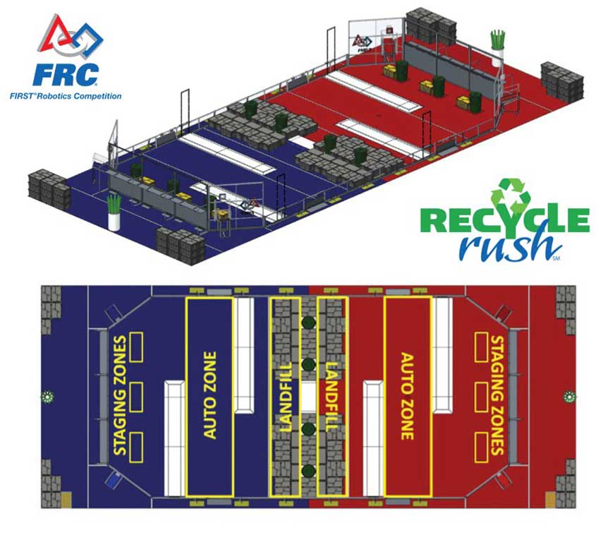
Part of this investigation is to take a look at the situation and problem of the FIRST robotics game, then coming up with unique working designs that you can use to build in SolidWorks. There will be several resources found on the school server in your Pickup folder that you can use such as the game manual, support docs, and related presentations. Below are some link resources to help with the steps to this activity
- 2015 FRC Game Animation - RECYCLE RUSH
- FRC 2015 Dallas Regional Final 2
- FRC 2015 GTR Central Regional Finals 1
- Team 865 WARP 7 - IRI Application Video
- 2015 Einstein FRC Champs - Quarterfinal 1
- Einstein Can Race Compilation
- Archived Game Docs including 2015 Manual
- Wikipedia on FIRST Robotics Competition (FRC)
- Karthiks Strategic Analysis
- Robot Design Steps/process, source
- Engineering sketch/drawing standards
- Sketching Technique 1
- Sketching Technique 2
![]() Remember to check your school server Pick-up Folder for additional related support resources and documentation that may help with this unit activity.
Remember to check your school server Pick-up Folder for additional related support resources and documentation that may help with this unit activity.
Robot Considerations and Support
Prior to actually designing a robot to compete, here are some areas to research/review:
- SPICE design process - robot design and build steps identified
- FIRST robotic competition, game process, and robot requirements/restrictions
- Realistic simple robot designs and their functions
- Related materials, support strength, costs, and efficiencies
- Specifications, measurements, and calculations
- Fastening, joints, linkages, and mechanical movement
- Programming, control, and sensors
You will need to look into the above areas by doing further research, talking to your peers, consulting with expert teams, and your peers to generate related working ideas worthy to challenge the competition.
Expert Areas
Students select an interested unique area from the student expert management sheet found in the PMT pkg, one which you would be lead expert in that topic area. Expert area topics are there to assist fellow peers with support information when coming up with ideas for their robot design and for additional support later in the course.
With each student/group researching different areas and then sharing those ideas, the class as a whole is a lot further ahead then just having everyone individually research it all. Each area is researched in depth allowing communication of ideas, and support for each other, making for a co-operative, collaboration, hands-on learning environment - PROFESSIONAL PEER COLLABORATION (PPC). When deciding on what to look up, keep in mind that this is for designing a FIRST robot, so the information must be supportive, helpful, and related to the FRC robot design.
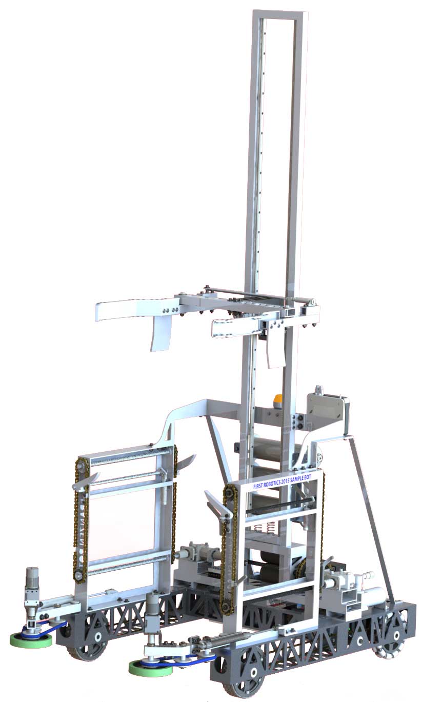
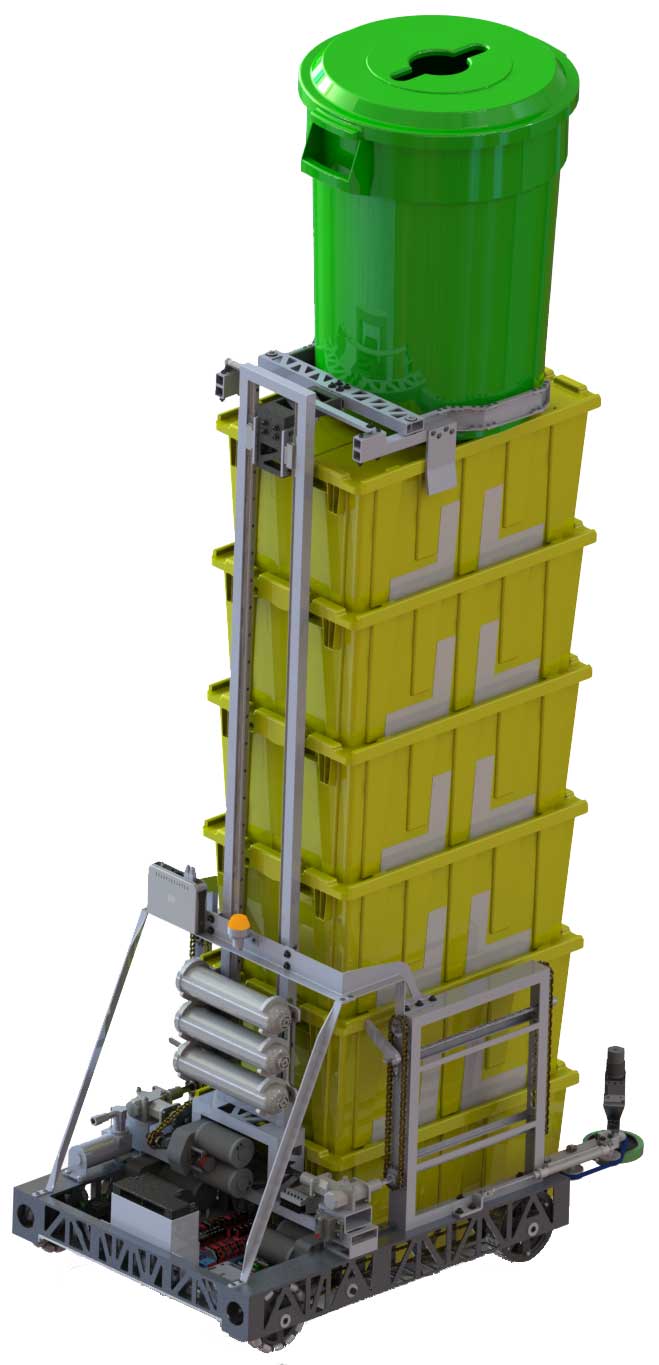
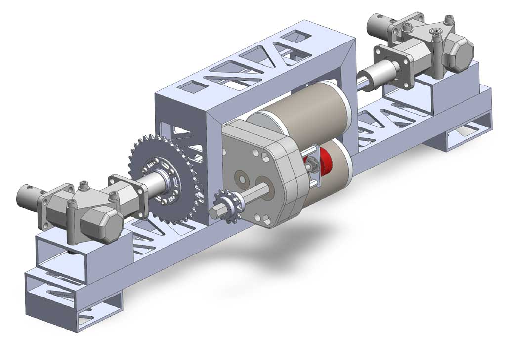
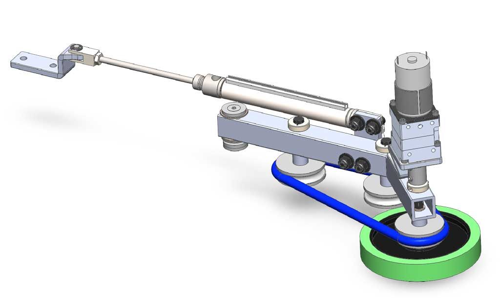
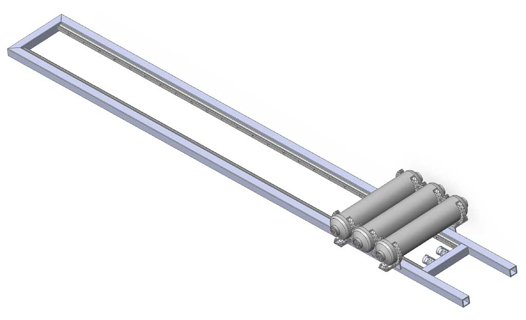
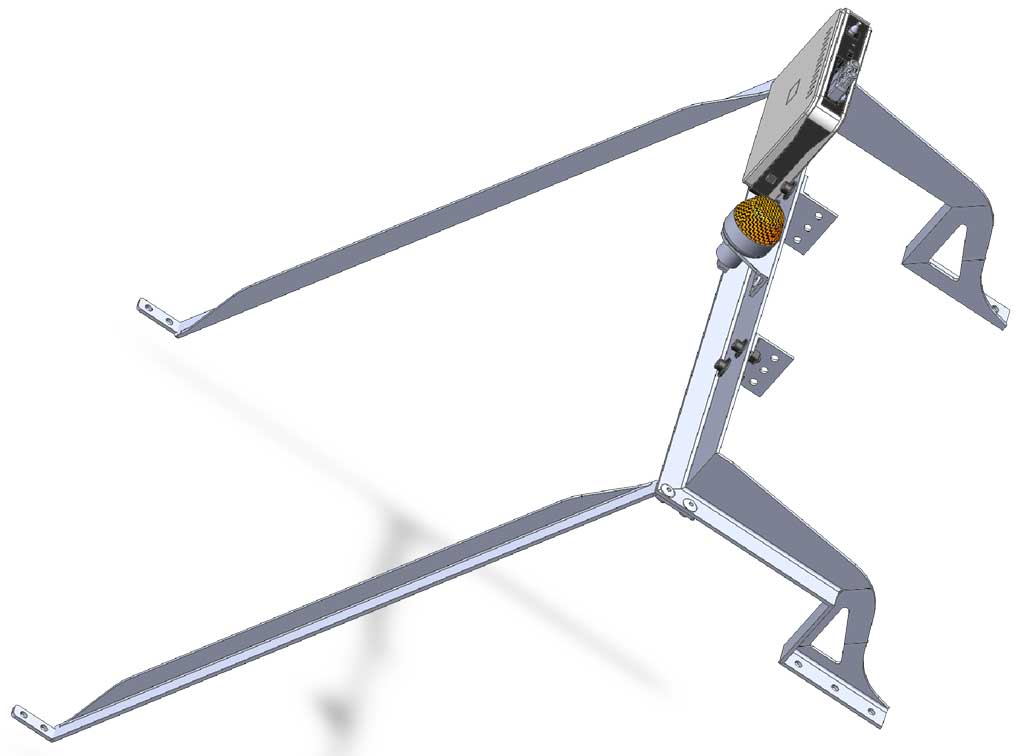
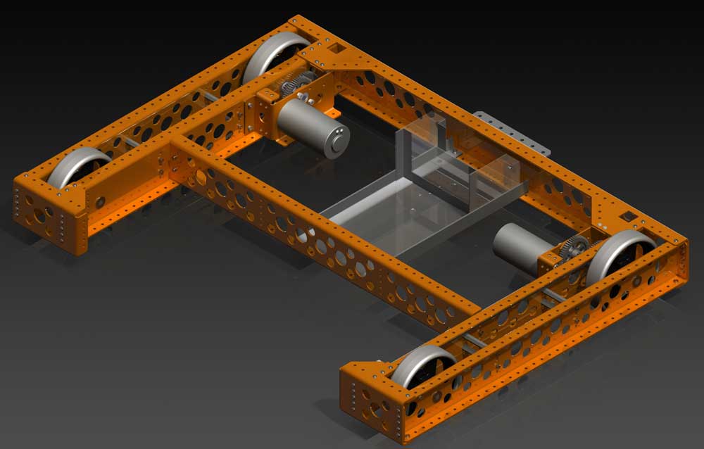
Sample Robot 3D Assembly Model and Renderings
Robotic design takes students through the process of designing a robot by looking at technical sketching, different types of drawings, dimensioning, engineering design process, mechanisms, gears, sprockets, mechanical joints, materials, 3D CAD model building, rendering, creating drawings, animations and a post reports.
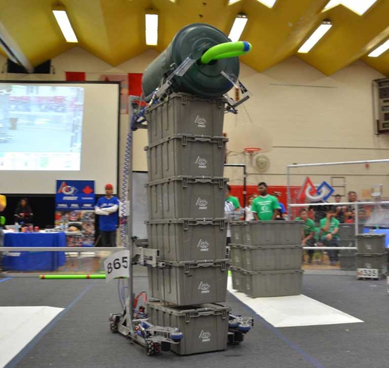
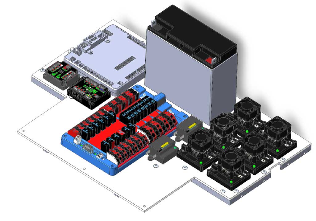
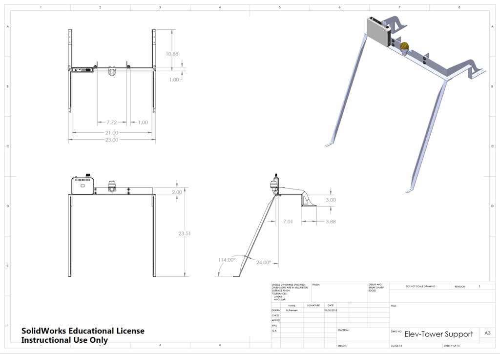
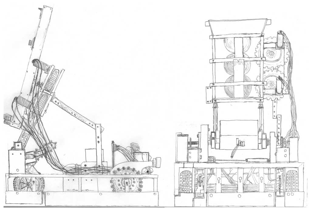
This robot design model was based off the 2015 manual, created for use with the senior design course as a focus on the design process application and as a Solidworks practice base to work with. Below are three views showing the sample robot design from different angles and positions. The first one, the gripper has been raised out of the tote chamber area so the different mechanisms can be seen separately. The second rendered image shows the totes and recycling bin held in place, and the third, shows the gripper in its home position. Here is an animation showing a full-size 360 robot rotation.

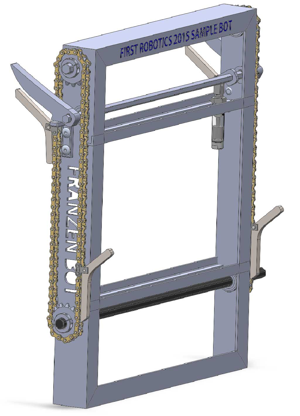
Main Robot Model Assembly Components
Below are the major individual component parts and sub-assemblies that make up the full robot model.
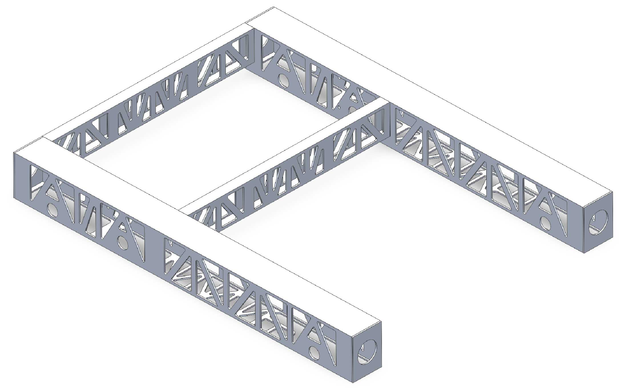
Frame
Elevator
Mid Frame

Gripper
Tower Slide
Upper Frame
Belly Pan
Robot Engineering Design Drawings
Below are some sample robot drawings are based on the 3D models. As this is a complex project, just the major components are shown here as there would be many individual parts in total that would end with numerous amount of drawings to show all details.
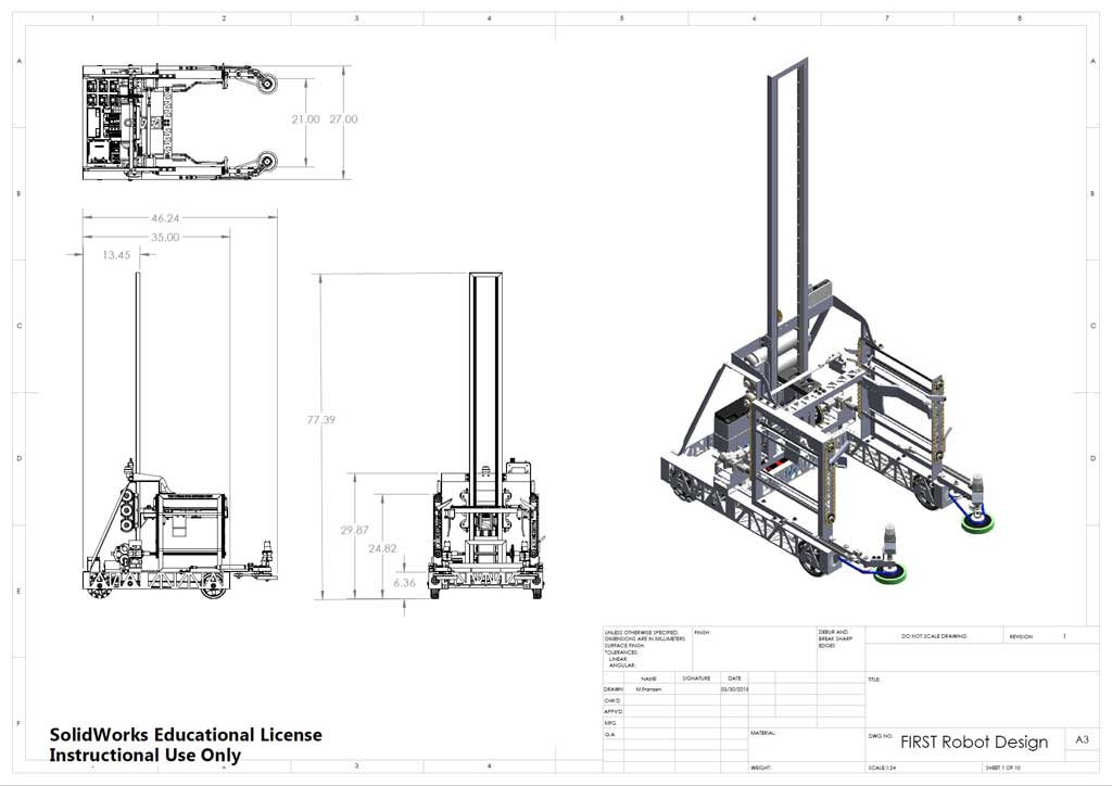
Model DWG
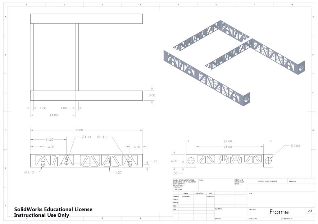
Frame DWG
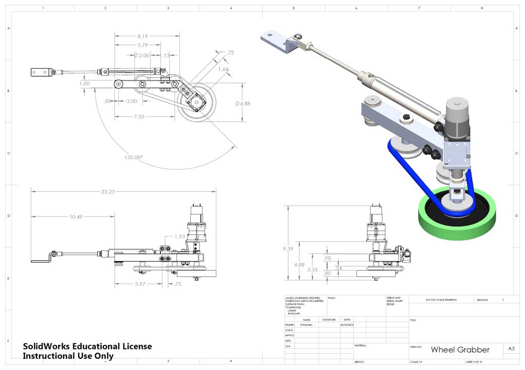
Grabber DWG
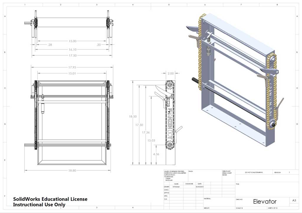
Elevator DWG
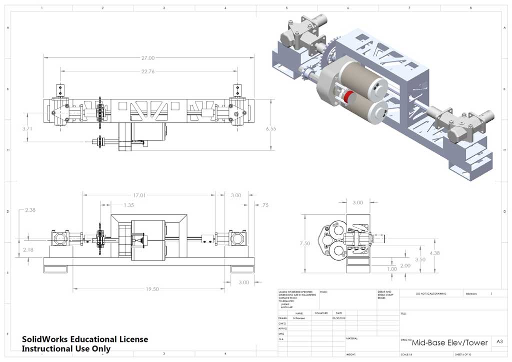
Mid Frame DWG
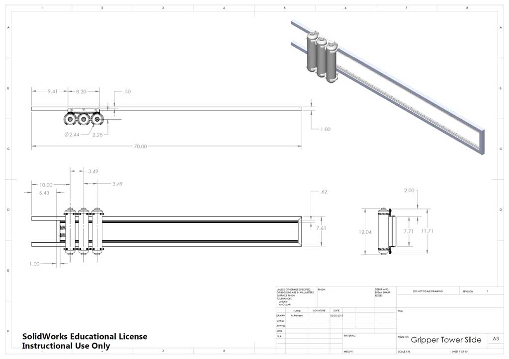
Tower Slide DWG
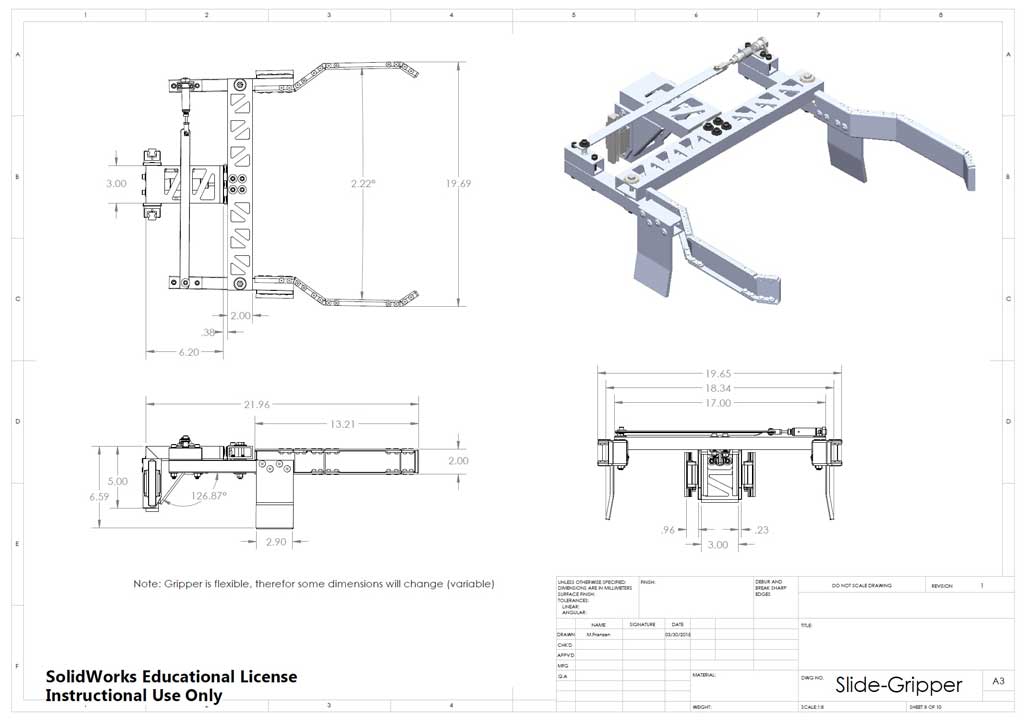
Gripper DWG
Upper Frame DWG
Sketch Issues and Concerns
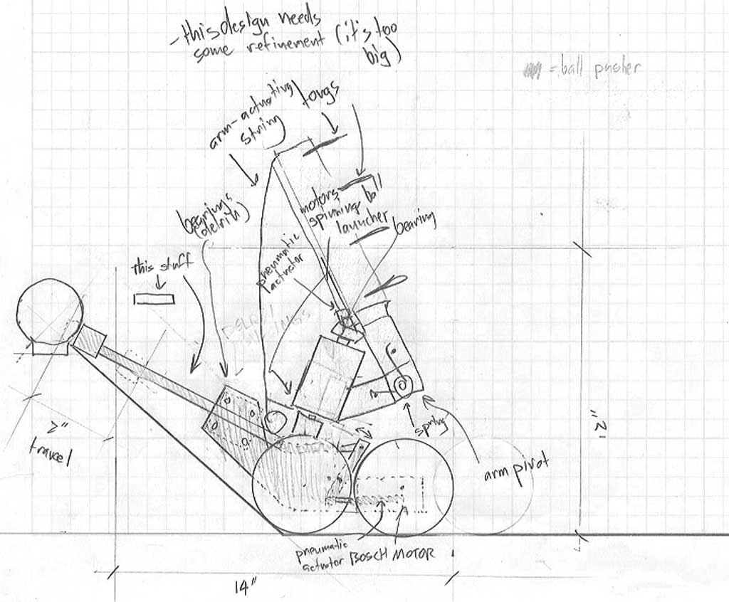
Below are some random sketch examples of robot ideas showing different issues that could be improved on, see if you can see what those issues are with respect to the technical sketching you have been practicing so far.
Sketch 1
Sketch 2
Sketch 3
Sketch 4
Sketch 5
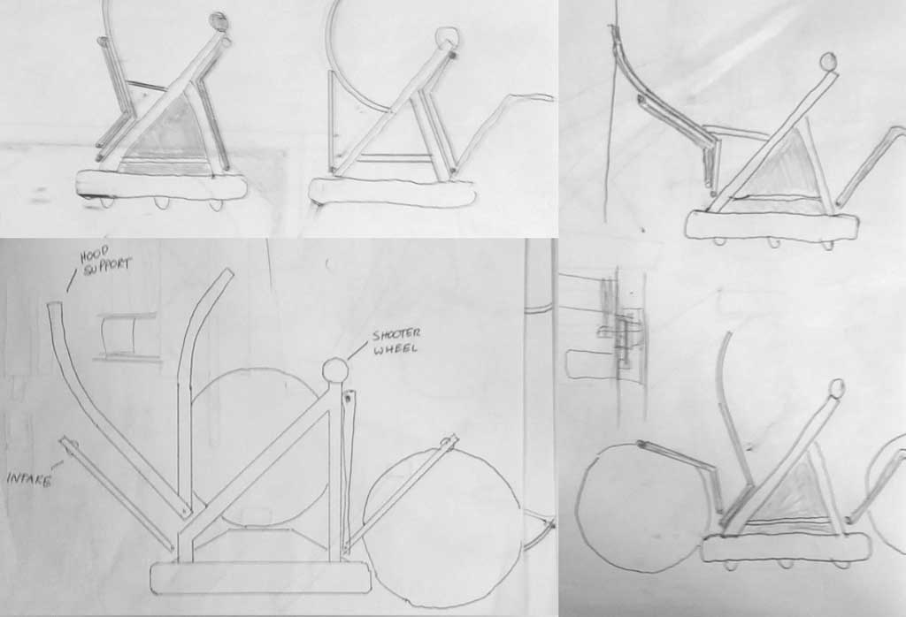
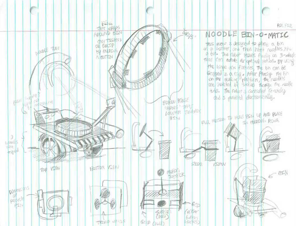
Robot Technical Sketching Samples
Here are some practical examples of what is required for your sketches. Compare and discuss the differences between the ones above and sketches 6-8 below.
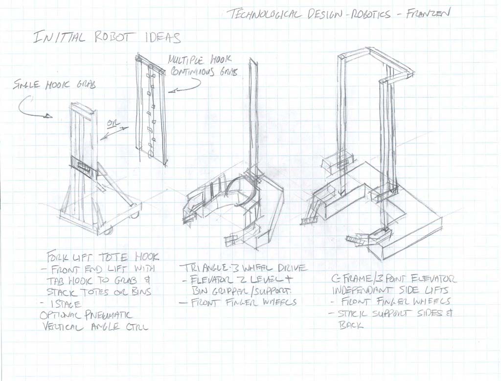
Sketch 6
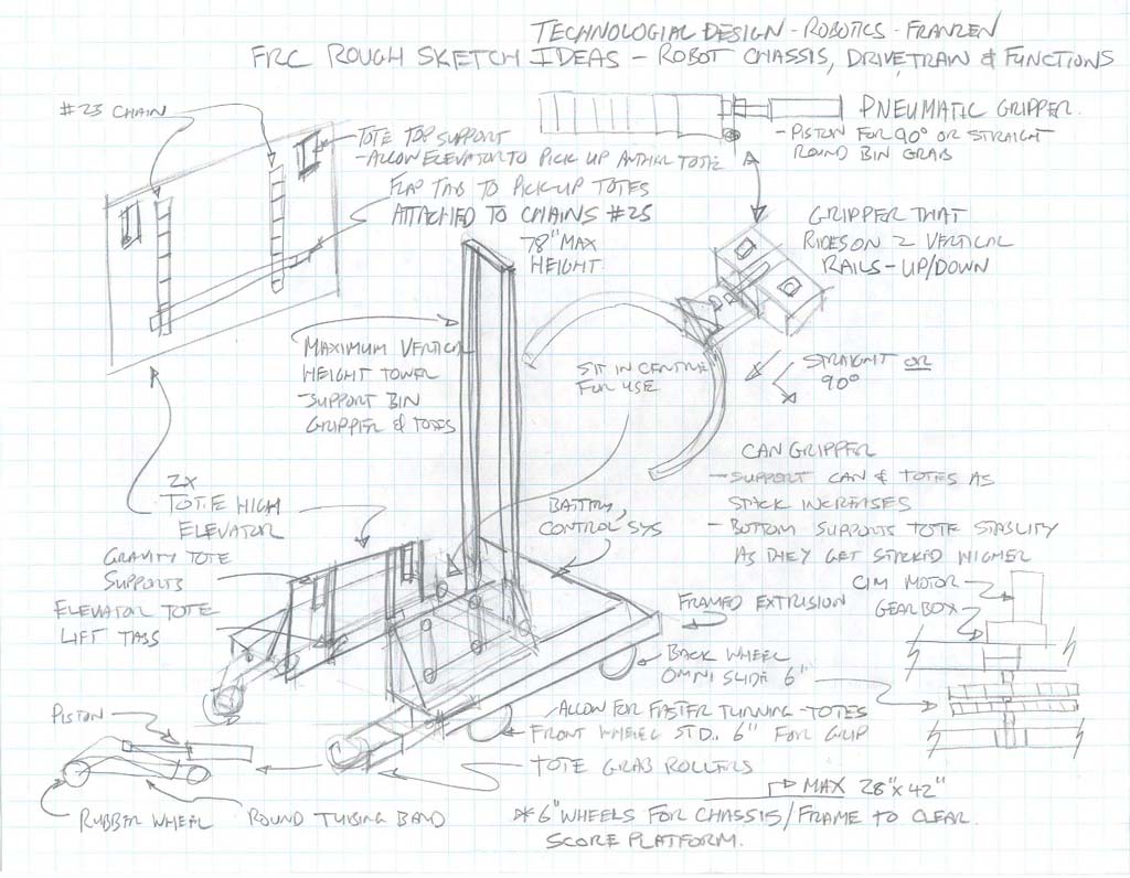
Sketch 7
Sketch 8
Sketch 9

Sketch 10
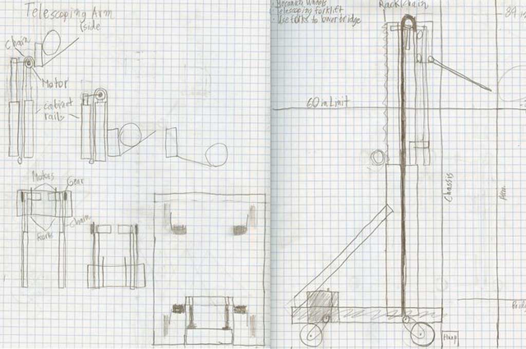
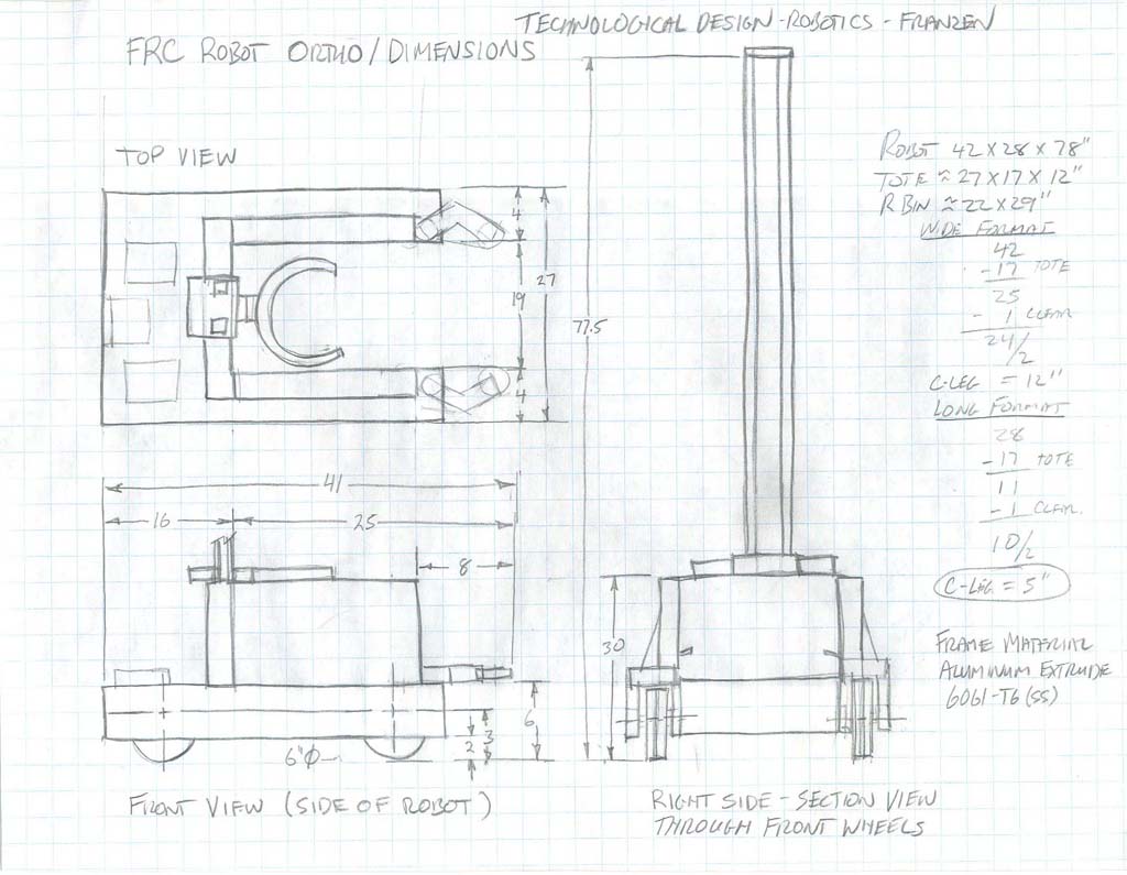
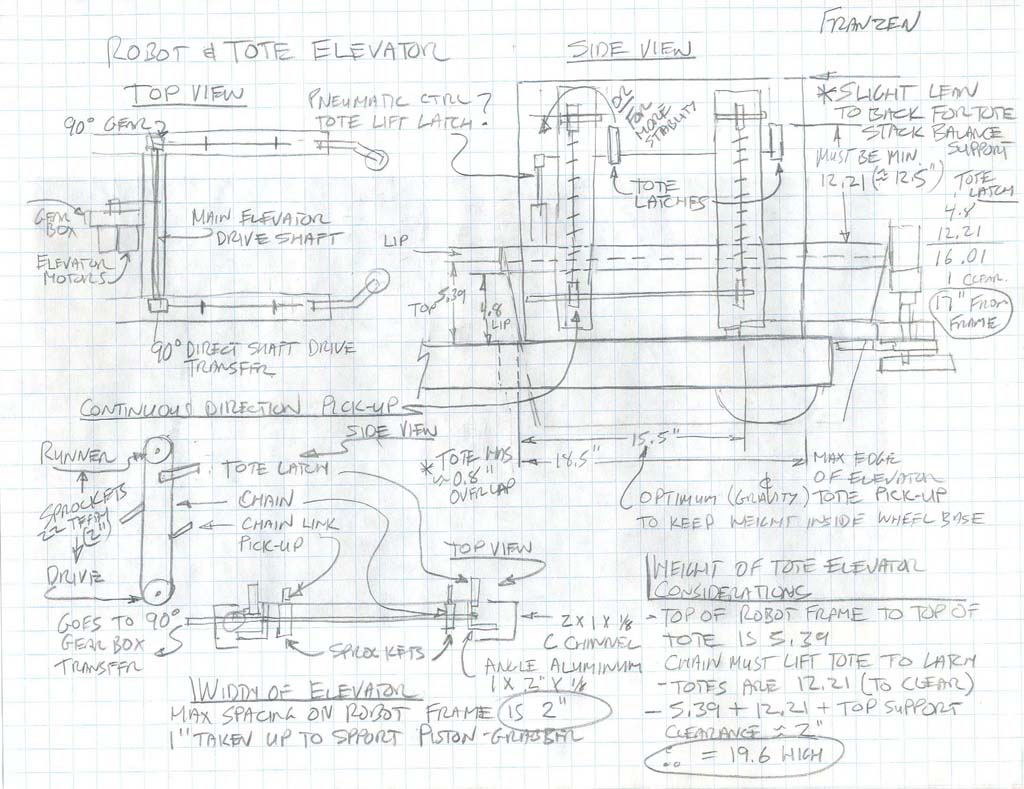
Sketch 9 show further detail of sketch 7, refining details such as clearances, further refinement of functions, mechanisms, and their capacities, actual numbers to prove things will fit/work with-in the confines of the scope and size of the project guidelines and robot tasks required (based on priority and strategy on maximizing points in the game done at an earlier point in time), showing/isolating major functions and expanding on those ideas with sketches showing working concepts.
Sketch 10 is calculations for drive and elevator speed/torque considerations to ensure that those mechanisms will work with-in required/needed tolerances. Further considerations on width of robot and functions, robot base and wheel clearance to clear stacking goal ramps.
Some issues you should notice looking at sketches 1-5 are:
- limit straight edges and use freehand for quick results
- graph paper can be helpful, but not absolutely necessary
- notations and labels help support the object idea you are trying to communicate
- space your labels and notations out away from your object and use leaders
- stay away from artistic sketching, stick with basic shapes, and clean lines for quick clean practical results
- keep initial ideas simple to convey major features and concepts
- refined ideas are generally more detailed with dimensions to lock down specifics
- think about what you are going to sketch and layout page so sketches make sense
- isometric can show a lot of general ideas while ortho can show more specific details
- initial ideas do not have to have all the answers, but show direction in ideas and/or design
Sketching your idea and making it as clear as possible with dimensions, notes, and details of your idea, will prevent you from wasting time when drawing up your ideas in CAD. Prototyping at this stage to see if certain ideas are unsure or unclear if they will work is also a possibility. Making something in CAD will take time and if your idea is not workable, then you may end up with a digital paper weight of waisted time amounting to nothing, so ensure you have taken the time to think through your design and sketched all the details to ensure you are on the right track.
Revit Detour Resources
Revit is a 3D CAD software tool used for building information modeling for architects, landscape architects, structural engineers, MEP engineers, and designers. Designing residential, commercial, and/or industrial dwellings require background knowledge related to engineering industry standards/codes, practicality, efficiency, environment, etc. which must be taken account when creating a design. Revit is a tool that helps support and communicate those designs accurately. Below are some initial resources to help with this process.
- Revit support
- Tutorial general overview, 15.46
- Simple house project 1, 29.37
- Simple house project 2, 23.09
- Standard home project, 60.00+
- Index of Revit support videos
- Revit Families
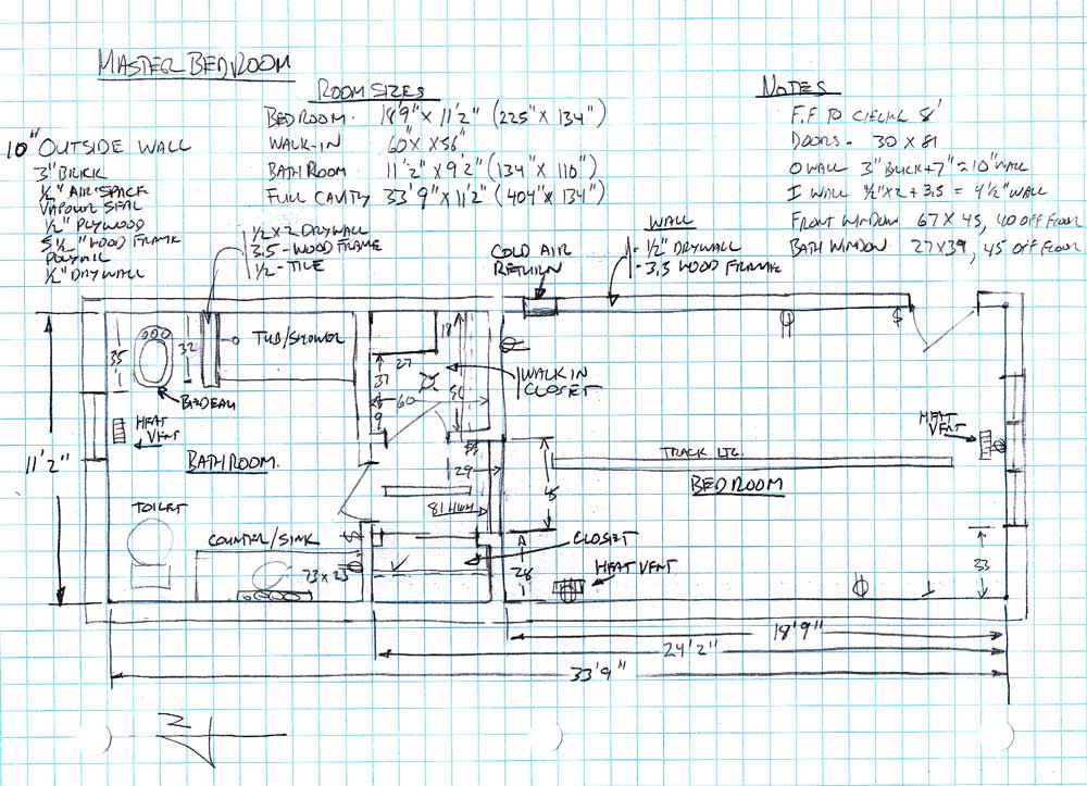
- Room design report
- Home design report
Rough Sketch

Room
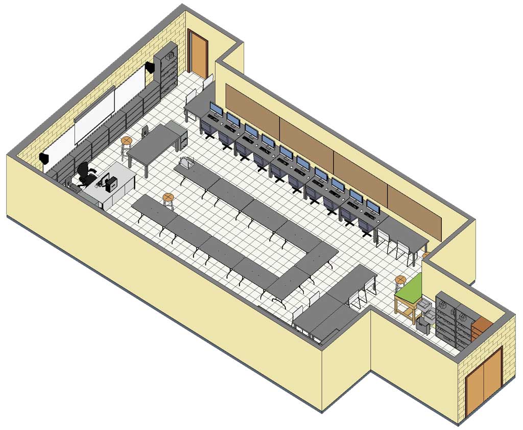
Classroom
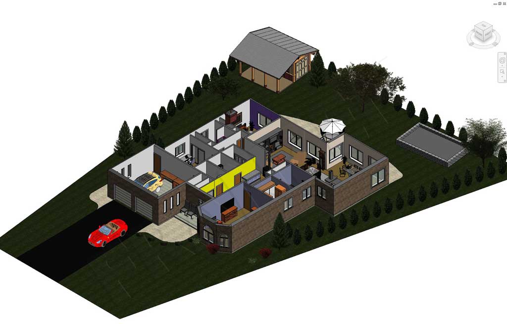
Home
Create/Construct:

Robot Research and Sketches:
In order to design something in a specific area such as a robot for the 2015 FIRST Robotics Competition, there must be an understanding of the actual game, robot components, mechanics, etc. Research must be done to establish a base to work from. Once there is a base of understanding and some technical knowledge, it is possible to start thinking of designs. Engineers understand the design process, have educational and hands-on expertise in their field so that they can look a need or challenge and be able to design and create a new working solution, that is helpful, and safe. To famiiarize yourself with the key details, answer the following questions on Robot Design Start.
Step 1, Research and Share
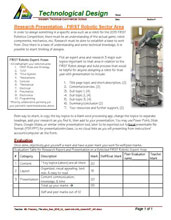
Pick an expert area from the Robotic Personal Sector Management sheet found in your PMT pkg and research 3 major sub-topics important to that area in relation to the FIRST Robot design and build process that would be helpful for anyone designing a robot for that year. Use the Expert Robotic FIRST Related Topic handout for a self checklist and self/peer evaluation for hand-in when finished presentation to class. Presentation to include the following slide topics:
- Title page with main topic and short description
- Contents/overview
- Sub topic 1
- Sub topic 2
- Sub topic 3
- Summary/conclusion
- Your resources and further support

For example ![]() Rules and Strategy for the 2015 FIRST Robotics Competition to include in your research; general game process, main rules/points, and robot requirements. Your presentation should include an introduction, game details, robot requirements, and must conclude with your opinion on the priority function(s) of the robot, in order to gain/score the most points. You will be expected to use multiple resources, some links and support may be found here, others on the web such as this
Rules and Strategy for the 2015 FIRST Robotics Competition to include in your research; general game process, main rules/points, and robot requirements. Your presentation should include an introduction, game details, robot requirements, and must conclude with your opinion on the priority function(s) of the robot, in order to gain/score the most points. You will be expected to use multiple resources, some links and support may be found here, others on the web such as this ![]() nice one-page summary of the 2015 FIRST Competition can be very helpful and handy.
nice one-page summary of the 2015 FIRST Competition can be very helpful and handy.
Step 2, Identify and Apply the Design Steps (SPICE)
Collaborate with your peers on the different expert areas related to the FIRST robotics completion that were researched. Feel free to share your findings to support each other in this assignment. Remember all of the resources you can also use in the our pick-up folder school's network under the Resource Library folder, you can use to help you with your ideas, process, and report. Taking some time at lunch or after school to visit the Warp7 robotic team robot lab to see and talk about past and current robots can be helpful. Also, you will want to check out the bottom half of your PMT pkg Gantt chart (picture below) which shows the graphical details of the robot competition design and build process, and is based off of a document called: ![]() Using the Engineering Design Process for Design of a Competition Robot, you could review.:
Using the Engineering Design Process for Design of a Competition Robot, you could review.:
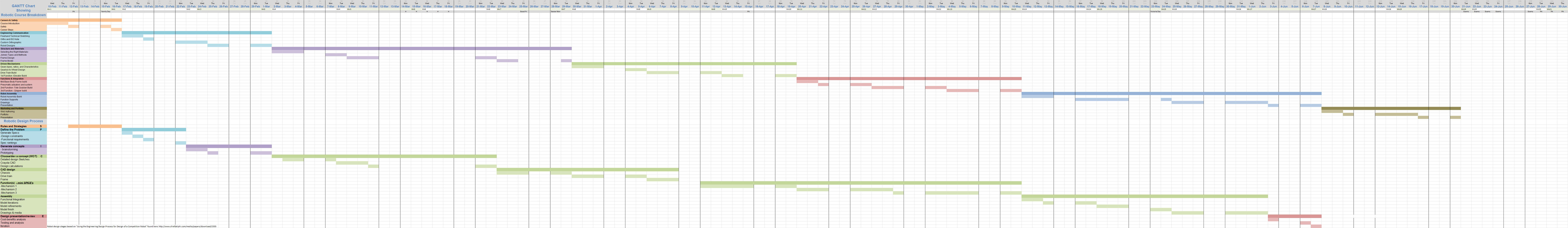
Gantt Chart, Top half - course breakdown and bottom half -robotic design process
Some key questions you may ask yourself and/or your peers to help with your SPICE report could be:

- What is the competition all about?
- What are the specific rules and robot limitations?
- Which game strategy will net me the most points?
- What functions do I need to prioritize in my robot design?
- What could those functions look like, what designs to use?
- What materials, products, standards, and ideas could/will I use?
- What are some things to further research to help with my unique robot design?
- How will I go through the steps from start to finish - my plan, to design a successful competitive robot design?
Identify and apply the SPICE model to the design of your robot. This will be done by reviewing the SPICE design model and applying it to the robot design process (collaboration of the 2015 FIRST robot competition, related expert area information, and your educated opinion on what will gain the most points in both strategy, function, and design) showing your depth of understanding of both and direction. One important key element to include in your problem will be what you think your robots design must include (functions) based on your opinion/priority of what the robot must do. Grade 11 students will communicate their unique designs/strategies/robot functions with the ![]() SPICE Applied - MS Word form showing their information/detail on each step of the design process.
SPICE Applied - MS Word form showing their information/detail on each step of the design process.

Senior 12's will customize their own custom robot design in similar fashion, which will require a ![]() proposal - MS Word form to be filled out and approved by the instructor, which you can also get from the school pick-up folder. The design must still follow the same process of current related project scope/size, but can be a different product, i.e. for example: we will be starting with creating a Weldment 2D Pro file and then using the Weldment Feature tool to create the robot frame. This is to be worked on till the end of the semester of which part of this will go towards the culminating.
proposal - MS Word form to be filled out and approved by the instructor, which you can also get from the school pick-up folder. The design must still follow the same process of current related project scope/size, but can be a different product, i.e. for example: we will be starting with creating a Weldment 2D Pro file and then using the Weldment Feature tool to create the robot frame. This is to be worked on till the end of the semester of which part of this will go towards the culminating.
Time line for this is a week, using today to collaborate with peers, and start filling in your information in your report, in class. Report to be handed in preferably working on the MS Word document version and handed in the drop-off folder next week. The following day (tomorrow), will start on the next assignment, so focus your time and effort to get this well underway. This way you can finish in the background while we focus on SolidWorks robot CAD work in class.
Step 3, Create Designs - Sketches
Start sketch designs of your ideas of a robot using your priority functions from the FIRST step above and include the usual: a header, layout with construction lines, technical sketching technique, and effective use of page space to communicate/show your ideas on three pages. Although you will not be sketching all aspects of the robot we will be working on, you will get a bit of a taste of what goes into coming up with a complex robot design by creating some initial real and practical concept sketches, mechanism details, and realistic refinement of a robot design. Each page is to include the (samples sketches 6-8 above and below) following:
- Three ISO robot design types based on your earlier function priority translating into what the robot may look like with short explanation of each, labels, and major functions/sizing on one page.
 Lay it out, use 3d ISO wire-frame stick frames initially, then add your thicknesses to your ISO view to make more realistic
 - One final sketched ISO, further refined with space to show those function and mechanism details with more notes/labels explaining your design. Again, layout page header, use 1/3 of page for your refined robot design ISO sketch with the rest of the page space to expand with further close-up details of those functions driven by practical mechanisms, notes, and details of each - example expand on drive system - motor and gear box drive location, sprocket/pulleys, number of wheels, type of wheels, location of wheels, etc.
- and lastly, one ortho (no ISO) showing the major components (frame/functions/mechanisms), size relationships, locations, major dimensions, with written FIRST robot size and requirements and any other major ideas. Layout with header and views with considerations of scale, size, dimension spacing, view spacing, and showing where all major functions are
To clarify, these sketch project assignments are not to be some vague obscure distant idea, but key working and practical concepts and ideas, that are functional, simple, and practical using/showing your technical sketching technique and skills. Here are some support suggestions on how to get ideas for your sketches:
- Collaborate with your expert area peer partners, their research, your research, and your own ideas
- visit to the FIRST robotics school Warp7 robotics team room may be helpful to see actual mechanisms and how they have build current and previous year robots
- Use the school class resource folder under library pictures, where you will find many pictures of robots from that years competition
Remember you are trying to base your design off of what you thought your priorities were, for that year's game, then translating that into tasks the robot must do, which are in-fact functions made up of mechanisms, usually custom and sometimes pre-made already.
Evaluation:
Complete all assignments for full marks. Expert presentation has an evaluation breakdown in the handout, while the SPICE applied has marks built into the form. Sketch marks are based off of the requirements in the instructions above and your sketching technique (samples provided with instructions).
| Evaluation Breakdown Component Descriptions | Marks |
|---|---|
| Always double check that you have completed all components for full marks. | |
| Expert Presentation - Topic content and presentation | 55 |
| SPICE Applied - Proposal for robot design steps and understanding | 25 |
| Sketched Designs - 3 ISO designs, labels, and details | 15 |
| Final ISO Sketch - 1 ISO design, functions, labels, notations, and details | 30 |
| Final Ortho Sketch - 3 views of bot, major components/dimensions | 20 |
Unit 3, Act. 3: Robot all Framed Up
Situation:
You have a completed your own basic robot design after looking at the game, working with your expert peer support, and prioritizing your robot's function to specific tasks. Students then communicated those ideas on paper through three sketches and should now have an awareness of the scope of this undertaking.
It is known now that having a finished sample robot design, will allow students to focus on reviewing the design process steps, ideas, and concepts and practice their use of CAD tools and knowledge, and learn new tools and process, further gaining more experience and learning. Students know that in the Engineering field, that there is a lot of team work, co-operation, and collaboration and this course will give a lot of opportunity to do this.
Problem/Challenge:
Apply 5 possible materials and required characteristics to a decision matrix (in your PMT pkg) to come up with a final material solution to a robot body.
Create weldment profiles to create robot frame model which will include:
- trim and caps
- drive wheel/gear-sprocket and bearing holes
- frame bottom cheesing
- Weld beads
- Model and DWG
Investigation/Ideas:

Making a Robot Frame
Using the sample robot frame as a way to familiarize yourself with some basic and common tools that SolidWorks has to offer and following some steps that will create a working end robot frame will help get you started on creating your own robot. The basics of engineering communication you have already learned such as selecting the correct front view, best way to place dimensions, best angle for an isometric, etc. Using SolidWorks has many ways of creating virtual models of your design and this is your opportunity to learn these steps that work for you. Later you may find an easier, faster, and/or better way to draw it, which will come with experience. It is important to get into the right habits and apply engineering standards as you create your designs.
Later on in this project, you will have the challenge of creating your own frame design and below are also some key points and ideas that should be considered when finalizing what you will be drawing for your frame. There are many considerations and decisions you will have to make to refine your direction with your robot design and specifically your robot frame so that it will support all of your robot components and robot task abilities.


SolidWorks General Info and Tips
Here are some key pieces of information and tips that will help with your drawing designs. These should be reviewed as they will be helpful throughout your 3D CAD design/drawing process.
- Inference lines are doted lines as you sketch when your pointer comes near reference points
- Co-linear lines go the same direction
- Coincident are two lines or shapes that lie exactly on top of each other
- Relationships selecting using Ctrl
- Use, create planes, (4.24) for further geometry
- Triad XYZ and Origin
- Save all project model and drawing files in the same folder and keep file names short, consistent, unique, and descriptive
- lines - go back on to original line to get arc
- Make sure common material profiles you use are easily accessible/low cost at your local supplier
- Use minimal different materials, components, and sizes when possible, keeping design make-up simple
- Avoid using angles greater than 45 degrees, hard to fabricate in real world
- Mouse gestures right click on background to get context sensitive tool icons, use Options - customize tool-bars, shortcut bars, commands, menus, keyboard, mouse gestures to add buttons, icons, etc to your liking
- Use S for context sensitive tool bar
- Use search command tool at top for quick access to tools
- Right mouse button - best friend, pausing with mouse will give you other options
- Design intent should be practiced to become second nature (practice and planing up front will save you a lot of time and effort). It is the way you apply relations, dimensions, and/or equations in sketches or features
- Initial drawing, don't concern with dimensions until you have looked at relations between sketch entities and model geometry first to support design intent
- Good practice to save up-front and Ctrl s to save as deemed necessary
- Draw on plane you want to show in dwgs
- Use origin reference anchor for your part, as good practice
- Ensure 2D sketch is fully defined, (2.38) before extruding
- Select multiple entities - use Ctrl or left click and drag, then pause for context sensitive tool bar
- Use = in dimensions to use equations with other dimensions in dimensions to allow dynamic relations, (36.54) to other sizing changes
- Can use multiple contours, (5.15) in a single sketch with the features extrude process to speed up modeling process flow, but be careful not to cram too much into one sketch
- Use part reviewer to study other peoples parts

Weldments in SolidWorks
Weldment has a unique tool set for designing structural frames, although it does not have to be used with weldments They are a multi-body part file similar to assembly with some limitations. This has the advantage of having no extra files to manage. The weldment feature comes with key tools and properties. Cut list and bill of materials (BOM) can be shown and edited using the properties of those components in the weldment. Custom weldment profiles are found using options to find location, and need to have three levels of folders to save to a new location in the form of standard, type, and size. With your custom profiles you will want to add references, construction geometry, centre lines, etc, then choose sketch and save as, in the proper folder, as library feature part file type. You can also download using the in-program design library and put in appropriate folder and/or download from on-line sites such as Bosh, Unistrut, Engineers edge, etc. as engineering materials for profile sketches that you can simplify for your design builds.
- Custom Weldment Profiles, 5.29
- Creating Custom Weldment Profiles, 5.30
- Custom Configured Weldment Profiles, 4.56
- Creating and Referencing Configurable and Custom Weldment Profiles, 6.46
- Custom Weldment table driven Configurations, 6.10
- Custom Weldment Profiles in detail Plus Importing, 11.55
- Creating Custom Weldment Profile Using Toolbox, 3.13
- Editing Weldment Profile Custom Properties, 2.56
- Guide to Solidworks Weldments
- Extruded Frames,16.58
- SolidWorks Weldments 101 - Simple Table,16.44
- SolidWorks Weldments and Frame Stress Analysis, 20.10
- Weldments Basic Tools and Methods - groups, locate profiles, & trim bodies, 12.06
- Creating End Caps, 4.00
- Creating Weld Beads, 4.00
OnShape Support links
2D Profiles
Making and naming your own 2D profiles for use with the weldment tool should include simple descriptive naming, material details, property descriptions, tables data driven profiles if several similar profiles types are needed, and saving in a two level deep folder such as a folder file system, folder type profile both inside a custom folder added to the file locations tab in the global options. Here are some common acronyms that you will want to include in your file naming to keep file names relatively shorter:
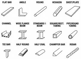
- CHS - Circular Hollow Section - commonly known as pipe or round tubes
- RHS - Rectangular Hollow Section - commonly known as rectangular tube
- SHS - Square Hollow Section - commonly known as square tube
- RSA-e - Rolled Steel Angle equal is normally called an angle or equal angle
- AL-A - Aluminum Angle
- RSA-u - Rolled Steel Angle unequal are called angle or L-shape
- FLT - Flat sections
- PFC - Parallel Flange Channel is normally called a channel or a C-section

Common naming convention that shows the detail of the object in the 2D profile name would look something like this as an example:
- 4.0x3.0x0.125-AL-RHS-6061T6.SLDLFP for aluminum rectangular hollow section that is 4" deep by 3" wide by 1/8" wall thickness with a material grade of 6061T6
- 3.0x1.0x0.125-AL-RHS-6061T6.SLDLFP for aluminum rectangular hollow section that is 3" deep by 1" wide by 1/8" wall thickness with a material grade of 6061T6
As the two above are from the same rectangular hollow section family type, they would be in the same Type folder. If you had several different sizes in the same type of shape, a ![]() table could be made, (6.11) to save time and repetition of drawing several of the same shape but different sizes. The above two examples above happen to be the two sizes and type needed to create your sample frame. You would also want to fill in the description for your 2D profile (access by clicking the property icon at the top) so that cut lists can be later made which would have the appropriate names and also updating the material grade in the profile tree.
table could be made, (6.11) to save time and repetition of drawing several of the same shape but different sizes. The above two examples above happen to be the two sizes and type needed to create your sample frame. You would also want to fill in the description for your 2D profile (access by clicking the property icon at the top) so that cut lists can be later made which would have the appropriate names and also updating the material grade in the profile tree.
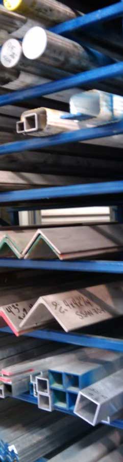
Local Metal Suppliers
When creating 2D profiles for use with your weldment, suppliers will have the standard sizes they usually have in stock and may also have drawing files. Complex extrudes can also be downloaded and then used to create your 2D profiles usually simplifying to suite model build. The worst thing is designing something with an odd size or unavailable size of material, later finding out that it is not possible to get or is not readily available. Here are some local suppliers that you can check out for your specific needs.
Folder Organization and File Naming Conventions
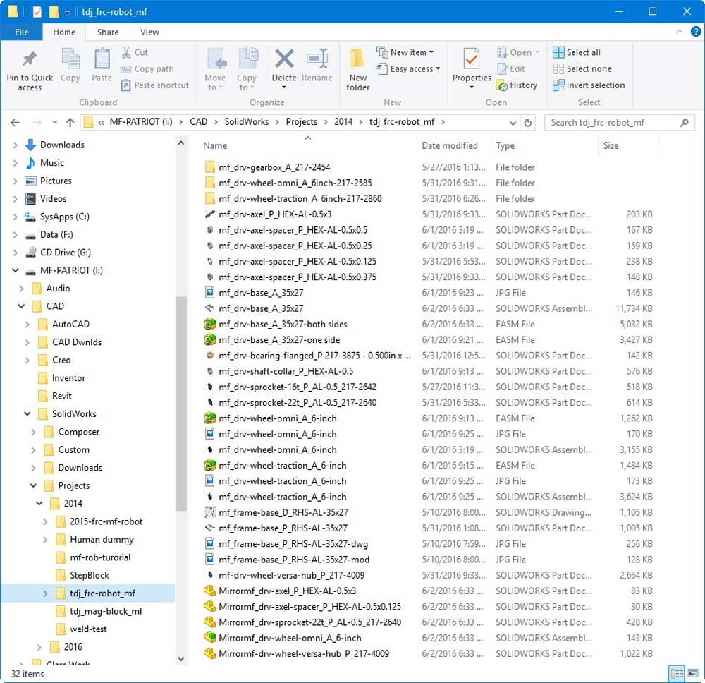
Generally if the design project is simple and not to complex, one folder is sufficient. When you have larger more complex project, a single folder can still work well with files named appropriately (consistent file naming convention), which a lot of professionals lean towards to. Folders can be helpful to keep files organized in specific situations. For example importing a wheel, gear box, and/or pneumatic piston assembly with lots of parts (lots of files, unconventional file naming, etc) would benefit from creating sub-folders and bring into your master assembly, keeping all loose files of that sub assembly together, easier to find and if necessary edit. Further nesting folders is not recommended and it is better to keep all parts, assemblies, and drawings in the main project folder. When creating sub folders keep folder name short to the point similar to file naming conventions below without your name.

While on the topic of organization, when creating an assembly of complex project, i.e. lots of parts/mechanisms, use sub assemblies in your design to group those component functions or mechanisms, so that when reviewing in the feature tree, each sub assembly will have it's own thread of parts/components making up the sub assembly, again making for an organized view of all of your design.
There is a lot ways to name your files in SolidWorks. Generally the file name is generated using an agreed upon standard convention based on intelligent and sequential numbering to keep them short, organized and unique. You may have noted the descriptive 2D profiles above which can be reused throughout projects, and are named using folders and descriptive file names with size, shape, and type.
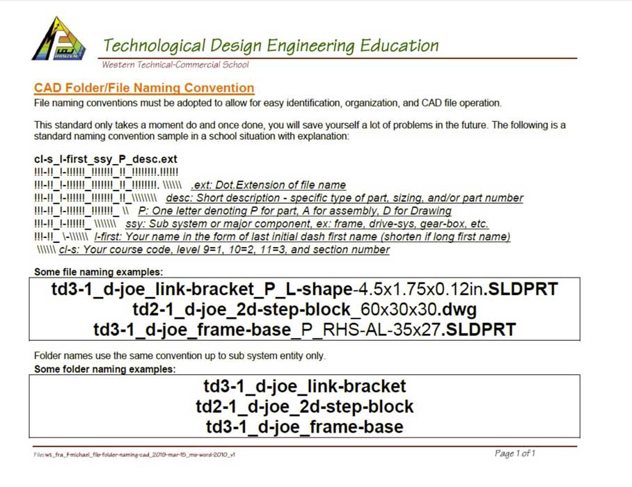
When creating part and assembly files, we will use the following simple naming convention: cl-s_l-first_ssy_P_desc for naming files using underscores to separate file name sections and dashes to separate words in sections.
- cl-s - course in two letters, level, and section
- l-first - your last initial, first name - short unique version 3-5 letters
- ssy - sub system or major component such as base-frame, drive-train, gear-box, tote-intake, elevator, gripper, etc
- P - is one letter denoting P for part, A for assembly, D for drawing
- desc - short description of component giving specific type of part, possibly sizing, and/or part number to make it unique and easy to know what the file is

Examples:
- td3-1_d-joe_frame-base_P_RHS-AL-35x27.SLDPRT
- td3-1_d-joe_drive-train_A_4-wheel-chain.SLDPRT
- td3-1_d-joe_gear-box_A_vex-2-stage.SLDASM
- td3-1_d-joe_tote-elev_A_2-chain.SLDASM
- td3-1_d-joe_tote-elev_P_sup-side.SLDPRT
- td3-1_d-joe_tote-elev_D_all.SLDDRW
Other common names you might use may be: belly-pan, tote-intake, bin-vice, frame-mid, frame-upper, tower-slide, etc. Project folder follows the same, for example: td3-1_d-joe_frc-robot-2015. Remember it may benefit you to put downloaded assemblies into a sub-folder of your main project folder for organization with appropriate naming convention. By taking a little time to name files/folders correctly at the beginning will save you a lot of trouble and frustration later. With you files and folders named correctly and organized, the more parts and assemblies created and/or brought in, will allow you to find and work with them much easier. On a side note, taking a look at ![]() SolidWorks File Management will show how the SolidWorks file structure and management works, which can lead to a better understanding on why file management needs to be carefully managed.
SolidWorks File Management will show how the SolidWorks file structure and management works, which can lead to a better understanding on why file management needs to be carefully managed.
![]() Want to save yourself a whole bunch of frustration, marks, and time, take the time to name your file/folder properly the first time. It may take a few seconds more and later you will be glad you did!
Want to save yourself a whole bunch of frustration, marks, and time, take the time to name your file/folder properly the first time. It may take a few seconds more and later you will be glad you did!
Coming up With Your Own Robot Frame
Creating robot frames can be designed multiple ways using different materials and build processes. Using your expert areas groups to help with questions and directions may help you with your decisions. Reviewing robot design briefs, other robot designs, and related documents can be helpful with narrowing down your direction on the frame.
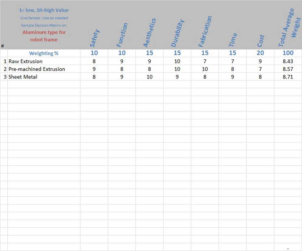
The decision matrix is a tool that can be used to make a quantitative decision when faced with countless variables that can be hard to narrow down to the right option by itself. Decision matrices can help you select the best option in several situations such as prioritizing tasks, problem-solving or even establishing arguments to defend a decision you may already have made. This tool was first created by professor Stuart Pugh and so sometimes refereed to as the Pugh method, grid analysis or the multi-attribute utility theory which removes subjectivity and adds quantitative values to a final choice. One additional consideration is taking into account the qualitative (a feeling, intangible, directive, etc.) argument may sway the final choice of your quantitative option.
Using provided Professional Management Package (PMT) will support your process and should be used. Specifically the decision matrix table can make complex decisions easy by adding your key components/ideas and basing them on several common variables to see which is consistently the best. The following considerations should be looked at as part of your process in your frame design.
Related Resources
- Decision Matrix Analysis
- What Is a Decision Matrix?
- Decision Matrix, 4.05
- Make the Best Choice with a Decision Matrix, 807

Design Considerations
Frame design must support the entirety of the robot. There are a lot of ![]() robotic related fields and information that overlap, so a broad knowledge base in several key areas really helps to not only see the big picture, but also the understand the smaller details also. This includes the drive train, electrical, electronics, mechanisms, and functions. It may most likely also include pneumatics which will entail a controller, valves, pistons, air reservoir, pressure regulator, and possibly an air compressor. The
robotic related fields and information that overlap, so a broad knowledge base in several key areas really helps to not only see the big picture, but also the understand the smaller details also. This includes the drive train, electrical, electronics, mechanisms, and functions. It may most likely also include pneumatics which will entail a controller, valves, pistons, air reservoir, pressure regulator, and possibly an air compressor. The ![]() drive train, (24.05) for example which may include the motor, gearing, transfer of rotational force to wheels/track will need to be considered in additional to the torque requirements, speed or speeds, possible wheel base, spacing, number, size, frame-ground clearance, and capacities. Weight distribution, type and location of mechanisms, and functions of the robot must also be considered. The robot itself has size, weight, and cost restrictions, which you will find in the
drive train, (24.05) for example which may include the motor, gearing, transfer of rotational force to wheels/track will need to be considered in additional to the torque requirements, speed or speeds, possible wheel base, spacing, number, size, frame-ground clearance, and capacities. Weight distribution, type and location of mechanisms, and functions of the robot must also be considered. The robot itself has size, weight, and cost restrictions, which you will find in the ![]() FIRST FRC 2015 robotics manual. The following are some general considerations to keep in mind with the frame design:
FIRST FRC 2015 robotics manual. The following are some general considerations to keep in mind with the frame design:
- Must support all components
- Must be rigid and strong where needed
- Must be under size, cost, and weight restrictions
- Modular for repair, replacement, and maintenance
- Type of material and build process
Using SPICE as a guide to understand what you need to do to accomplish a successful robot design will need new knowledge, communications, and understanding to apply and solve your challenges. Taking a look at ![]() Myth-busters' Adam Savage on Problem Solving: How I Do It, (6.40 - 23.22) is something that could give you a different perspective and reinforce steps that we have already considered. Another corporate
Myth-busters' Adam Savage on Problem Solving: How I Do It, (6.40 - 23.22) is something that could give you a different perspective and reinforce steps that we have already considered. Another corporate ![]() 7 step problem solving, (4.38) process using different words but similar process of steps and additional insight may also be helpful and reinforce the importance of taking the right steps to accomplish your goals.
7 step problem solving, (4.38) process using different words but similar process of steps and additional insight may also be helpful and reinforce the importance of taking the right steps to accomplish your goals.
Material Considerations

As weight is not only a factor but also a limitation in the restrictions, what material you use for specific purposes must be considered. Strength and support are critical to the operation and function of your robot design. The amount and type of materials needed to be displaced throughout your robot including your frame must support your robot's ability to complete the tasks. Usually this means excellent maneuverability and effective functions. Not only different types of materials such as aluminum, steel, carbon fiber, PVC plywood, sheets and polycarbonate , but also the shape such as sheet, tubing, angle, C channel,
- Best frame building material
- Mat Web Material Database
- Materials for robot building
- Bosch Rexroth Extruded Aluminum
- Esto Connectors
- Titanium vs Aluminum
- Material Selection Charts
- 7 Things to consider when choosing an aluminum grade
Process Build Considerations

How the design will be built needs to be an important factor on how and what you design. Virtual designs need to take into account the manufacture steps to make the design. Machine processes are important to understand so that designs make the build process effective. Looking at different ways to build a component must take into consideration the tools and services available to create or build those parts. How do you join corners, ends, supports, functions, components such as using rivets, tubing inserts, bolts, welds, gussets, etc. For example, if you do not have sheet metal tools, but have basic machining tools, then you may want to consider using extruded shaped material, but then buying connectors will be very expensive where if you use tubing and you can machine or weld, parts together, it would be cheaper and lighter.
- Robotic build Materials and fastening
- Joining aluminum
- ITP Fabrication
- Build your Everything Really Fast
Create/Construct:


Design Matrix- Deciding on Your Material
Using the Professional Management Package (PMT) , use the sample design matrix sheet under tab 6 (this is one of many formats/templates you may find out there) of your package to compare 5 possible materials to use for the robot frame based on the following common variables:
- Safety: working with, recyclable/environment, life span, robot protection, strong enough
- Function: does it do what it is intended, does it serve it's purpose, does it work
- Aesthetics: does it look good
- Durability: wear and tear, life span, reusable
- Fabrication: easy to machine/manufacture, easy to work with
- Time: is it hard to get, quick to machine, easy to transport
- Cost: is it relatively expensive, expensive to work with, environment waste
- Weight: comparison to other materials, heavier not good/lighter is better
You will need to do some collaboration, editing to the sheet supplied in your PMT pkg, deciding on materials, rating each of the materials with common variables, to get towards a solution:
Steps to Follow:
- As a group collaborate with peers to decide on the weighting of each of the above variables in terms of importance for your robot design/build, must equal 100%
- Review and discuss with partners the section: Coming up With Your Own Robot Frame - design and material considerations
- Individually add five different materials that could realistically be used to create your robot frame, ex steel, alum, wood, etc and place in first column under the weighting cell and modify title above from 10=high to 1=low value (because you are using 5 materials), and Material types for Robot Frame
- If not already added, add/insert column after Cost column titled Weight
- Decide on variable percentages for each in terms of priority with final variable total to be 100%
- Add the following formula for cell K3 which is the total of the first row of ratings of variables taking into account the % weighting you have collaboratively decided on and your 1 to 10 rating (Note dragging formula down, $ sign prevents auto increment for that variable): =SUM((C3*($C$2/100))+(D3*($D$2/100))+(E3*($E$2/100))+(F3*($F$2/100))+(G3*($G$2/100))+(H3*($H$2/100))+(I3*($I$2/100))+(J3*($J$2/100)))
- Copy the formula to the next 4 row columns by selecting the K3 cell, then click on the small solid corner box of cell and drag down to the next 4 cells
- The highest total average should be your decision matrix quantitative answer based on your ratings (do your peers agree?)
- Write under/below the materials section - next cell: if you agree with the final result, is there a qualitative factor(s) that may change your final decision, if so what and why - short answer?
Now that you have completed this project be aware that there are different formats of a decision matrix and can be applied differently to many different things that you may need to make a decision on. Keep this tool handy when there are too many variables/criteria to look at all at once.
Sample Frame
Create practice frame using the drawing sheet or edrawing supplied. The following are key steps that should kept in mind while working on the sample frame. Model and drawing files below show what the finished frame looks like and the sizing required. The instructions below are in-line with ![]() Extruded Frames,(16.58). Using supplied drawing below and the edrawing supplied in your pick-up folder, you can re-create the sample frame below.
Extruded Frames,(16.58). Using supplied drawing below and the edrawing supplied in your pick-up folder, you can re-create the sample frame below.
Create a 2D Sketch Profile
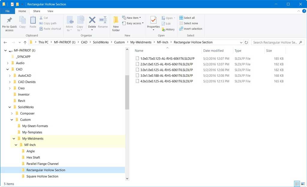
It is very common and easy to make most profiles from material sizes and shapes available from local suppliers. It is also possible to download profile sets or just grab a 3D model, then strip it down to a 2D simplified sketch. Below shows steps if you grab a 3D model, modify, then save as a library feature part. For the sample robot frame, you will create from scratch the 2 initial profiles needed, starting with step 3. Ensure you have reviewed the ![]() Custom Weldment Profiles, 5.29 video showing this process.
Custom Weldment Profiles, 5.29 video showing this process.
Set-up Custom Weldment Folder location
Before you create your library of profiles below, you will need to create a custom weldment folder for your 2d sketch profiles (see left image), then in options under file locations you will need to point SolidWorks to your custom weldment folder using Options >System Options >File Locations, select Weldment Profiled in drop-down menu, then add your "My-Weldments" folder address (should be on your USB flash drive for ownership and mobility). This custom weldment folder must be organized into two more sub-folders, showing the measurement standard, then the specific shape or type of profile material extrusion it will be. Later when you will be using your custom library profiles with weldment creations, SolidWorks will open a panel up on the left and have three boxes to confirm and access the correct profile needed.
If you are working on ![]() OnShape, review the What's New video showing the new Frame tool. Also as you don't have access to E-Drawings App, use the
OnShape, review the What's New video showing the new Frame tool. Also as you don't have access to E-Drawings App, use the ![]() OnShape Sample Frame Model for further dimension details as needed.
OnShape Sample Frame Model for further dimension details as needed.

Remember to name your weldment profile file names with the following convention. Examples:
- 4.0x3.0x0.125-AL-RHS-6061T6.SLDLFP - This file naming convention represents: aluminum rectangular hollow section that is 4" deep by 3" wide by 1/8" wall thickness with a material grade of 6061T6
- 3.0x1.5x0.125-AL-RHS-6061T6.SLDLFP - This file naming convention represents: aluminum rectangular hollow section that is 3" deep by 1" wide by 1/8" wall thickness with a material grade of 6061T6
Create Your Weldment Profile
- Find aluminum profile or make (3D content)
- If using an extrude, remove the extrude feature and determine what you need - what is really necessary, remove sketch relations and fix if necessary, keep features you want and simplify, remove excess geometry, and then clean up with trim
- 2D Profile from scratch, you will need to create two profiles for the sample frame, one 4"*3" rectangular hollow section tubing 1/8" thick wall and one 3" * 1.5" rectangular hollow section tubing also 1/8" thick wall
- Add construction lines and reference points to help with inserting on weldment frame
- Be aware that end points are needed and used in weldments, i.e. construction lines may be used for end points if necessary
- Select the material grade/type through the material type in the feature tree
- Update the description in the properties for this file using the properties icon top centre
- Save as a library feature part .sldlfp, [
 ensure you have the sketch selected in the tree prior to saving the library feature part file ] using file location in options which you can keep on your USB or local Drive so Solidworks has access to it while it is running, to your custom 2D profiles in your custom feature part library location

Sample 1
Profile
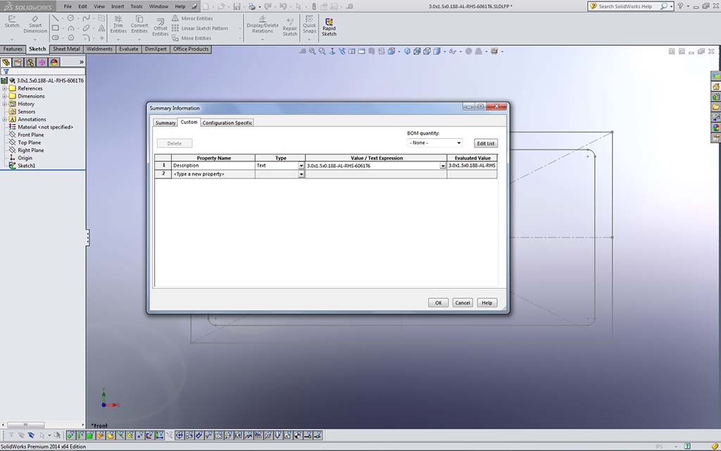
Sample 2
Properties
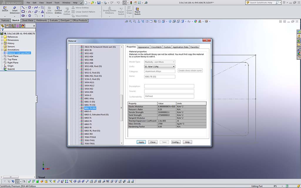
Sample 3
Material
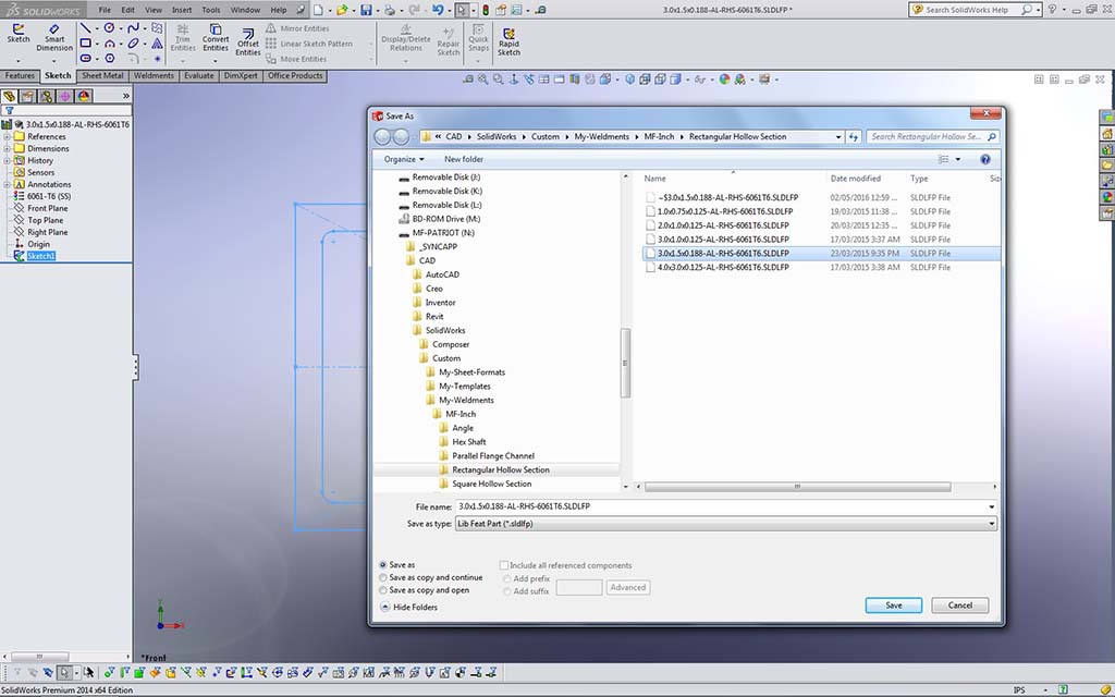
Sample 4
Save As
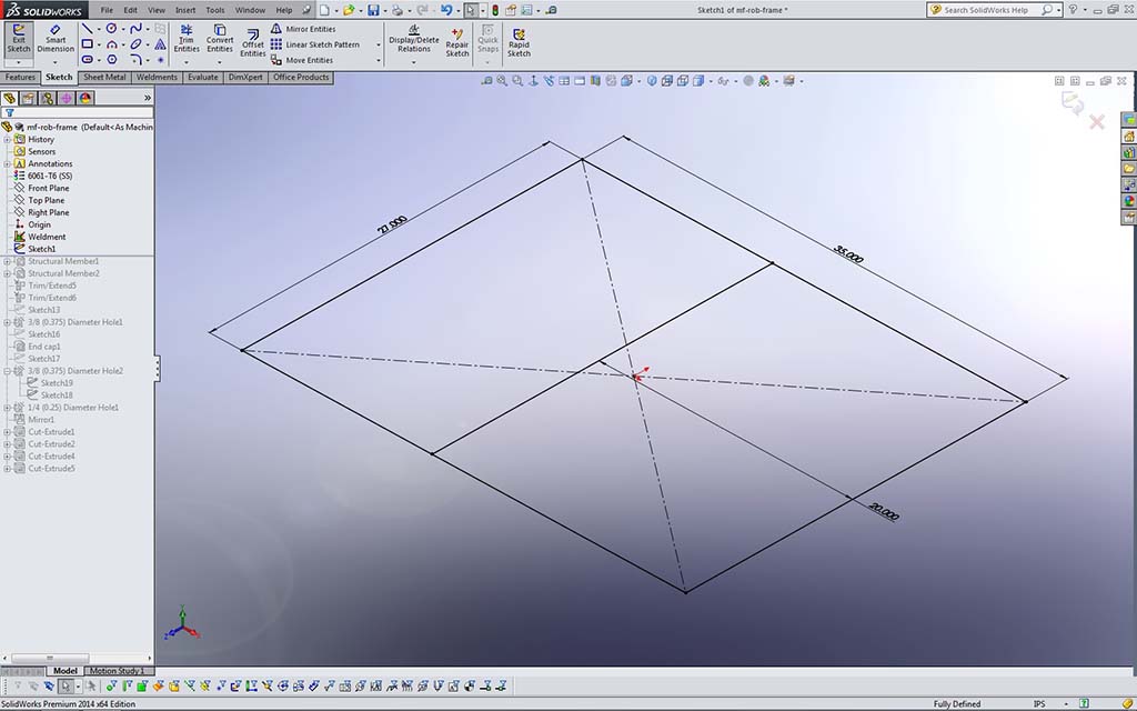
Sample 5
2D Sketch
Create a Sketch for Weldment
For the sample file the 3D Sketch tool is not necessary and the 2D will be fine. If we needed to do something more complex, as we will need to do later with the elevator frame support, then the 3D will be needed. Instructions are the same with the exception of working in three planes instead of 2. Make sure you create a folder name such as td3-1_d-joe_mf-rob to use for all your CAD files for this project. CAD files you create must use the correct file naming convention the first time you save, such as: td3-1_d-joe_frame-base_P_RHS-AL-35x27.sldprt. See folder- file organization and naming convention for more information.
![]() Note once you start working in a 2D sketch, you can not go into 3D for that same sketch, so if you know it is a complex sketch needing three different co-ordinate directions, then you should initiate the 3D Sketch tool first.
Note once you start working in a 2D sketch, you can not go into 3D for that same sketch, so if you know it is a complex sketch needing three different co-ordinate directions, then you should initiate the 3D Sketch tool first.
Points to Keep in Mind
- The 3D tool has more options, xyz coordinates, otherwise 2D will work fine
- Keep it simple, use snap to system planes
- Use centre rectangle for example (symmetrical)
- Cursor - red arrow will signify sketch plane you are on and use tab to change
- Sketch relationship along x, y, (or z for 3D) planes using the snapping feature
- Clean up the sketch, then add remaining dimensions
- Fully define all geometry (black) and ensure Design intent is considered, for example mid points may be used to keep things symmetrical
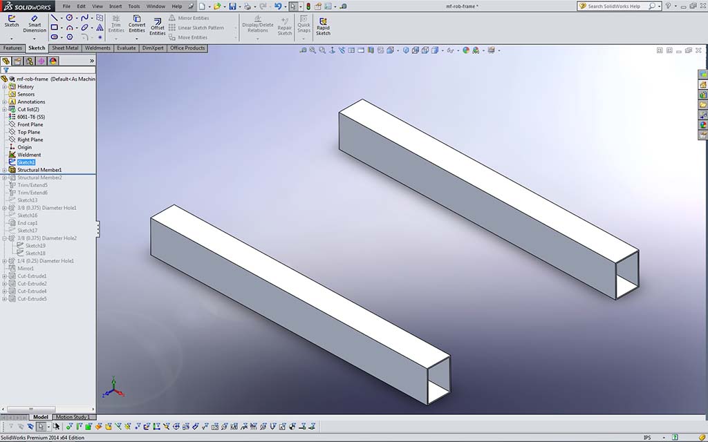
Sample 6
4x3-RHS
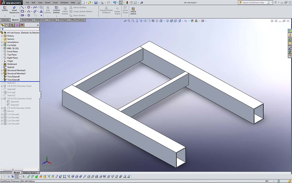
Sample 7
1x3-RHS

Sample 8
Wheel Bearings

Sample 9
Drive Bearings
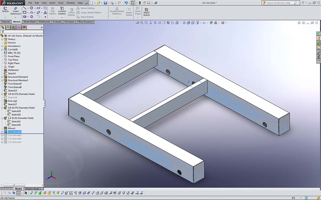
Sample 10
Bottom Sketch 1
Create the Frame
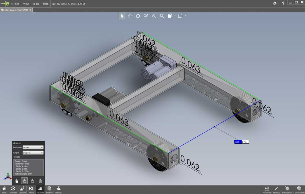
eDrawings App with Measure Tool
Looking at Sample 5 2D Sketch above, you will need to start creating a 2D sketch similar to the one in the picture. In order to know the exact dimensions for that object you are creating, eDrawings (a free CAD model, assembly, and drawing viewer already installed on your computers in class) can be used to get the frame details you need to draw your frame. Using eDrawings is intuitive and has a lot to offer such as ![]() looking at a model, assembly, or drawing file and see views. sections, and measure using the measure tool, 6.34.
looking at a model, assembly, or drawing file and see views. sections, and measure using the measure tool, 6.34.
In the pick-up course school network folder, are the edrawing files (accompanied with JPG's) for the robot we will be working on, including the frame. Go to Resource Library > CAD > MF Bot E-Drawings (recommend you make a shortcut to this folder for yourself) and you will find the whole robot, in project sections. You will need to open the first file: mf_drv-base_A_35x27.easm with eDrawings to view and measure what you are going to draw. You can use the Components filter tool in lower left, to Isolate just the frame by selecting it in the components list (4th from the top) and click on the Isolate icon near bottom, to get rid of all drive related components, and also right click on screen background, select View > All Annotations to turn off weld notations for a clean unencumbered view of just the frame.
Remember as you create your frame; name features in feature tree, add the summary information, properties, and select the material. Use the image steps 5 to 10 and If you are having problems, there are several related resource videos in the Investigation section near bottom of resource links above that you can check out for more support. The following are general points/steps you should be taking to add your weldment profile to your structural weldment robot frame 2D sketch starting with and shown in Sample 5 2D Sketch above.
- Use the Structural Member Tool on Feature tab
- Select profile
- Select 2D sketch elements to attach the weldment profile to
- Align and locate frame members if necessary
- Ensure corner treatment is looked at if necessary
- Use Groups - for more members previously selected for rapid creation
- Trimming - 2 ways - Face/plane or Body
- Face/plane may be a problem when selecting (FYI)
- Body Trim - suggest un-check Allow Extension
- Use the Cap tool to finish off open ends flush inside
- Create fillet and butt welds (note: back ends of bot is tricky) at joints (1/16" bead thickness TIG as your weld spec) and if they are not showing after applying, check in document settings, that cosmetic welds are turned on
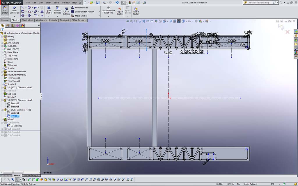
Sample 11
Bottom Sketch 2
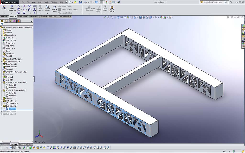
Sample 12
Side Sketch 1
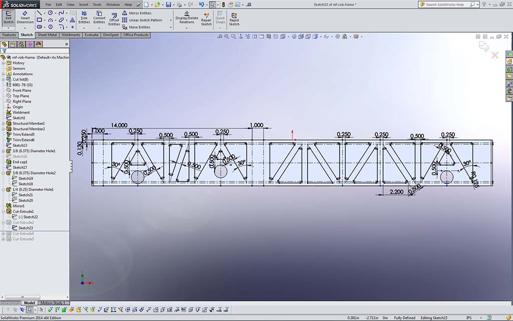
Sample 13
Side Sketch 2

Sample 14
Back Sketch
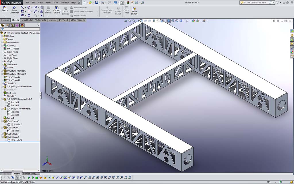
Sample 15
Model Finished
Note, to save time, improve file and computer performance, just do the bottom cut outs, i.e. so ignore Sample 11 - 15, as they are there just for show. Move to next section below:

Additional Things to be Aware of
- Use weld tool to show weld locations
- May use mirror tool to save time
- Update cut list if necessary - example same part reused several times - right click in tree to update, which will combine the same parts into one item with total number required
- Update the material type if necessary
- Custom components - add necessary properties in the user properties table
- Rename your features created in the model tree manager while they are fresh in your mind, as later when you may want to do some editing, it will be easy to find what you are looking for
Bearing, Gearbox, and Wheel Hole Openings
You will also need to create the holes for future bearings, gear box and wheel openings. Wheel holes on the bottom will need to be created on the bottom for wheels, drive sprocket, and chain clearance as shown in eDrawing file: mf_drv-base_A_35x27.easm you have been using. While doing the wheel cut-outs, you can remove some more material to get an idea on one method to remove weight, but still keep the structure intact. Do only the bottom, the sides are not necessary to do for this project. When sketching the cut outs for the wheels and material removal on bottom, note construction lines top and bottom (Sample 17 Bottom Cuts) are used to align all the opening cutout shapes and that the triangle shapes once fully defined are mirrored end to end (Sample 18 Triangle Pattern). Once one bottom piece is done and fully defined, you can, then ![]() mirror to the other side, 9.34 to save time (Sample 19 Mirror Cut). You will need to place a construction line through the centre to use as your mirror line. Removing the extra material (filleted triangles) adjacent to the wheel and gear box gear areas will lighten the weight of the frame while still keeping the strength of the Rectangular Hollow Section tubing structure at acceptable limits. Further reduction is possible working on the sides, but not necessary for this project lesson, so only do the bottom.
mirror to the other side, 9.34 to save time (Sample 19 Mirror Cut). You will need to place a construction line through the centre to use as your mirror line. Removing the extra material (filleted triangles) adjacent to the wheel and gear box gear areas will lighten the weight of the frame while still keeping the strength of the Rectangular Hollow Section tubing structure at acceptable limits. Further reduction is possible working on the sides, but not necessary for this project lesson, so only do the bottom.

Sample 16
Gearbox Mount
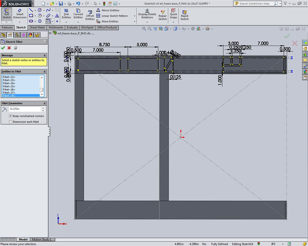
Sample 17
Bottom Cuts

Sample 18
Triangle Pattern
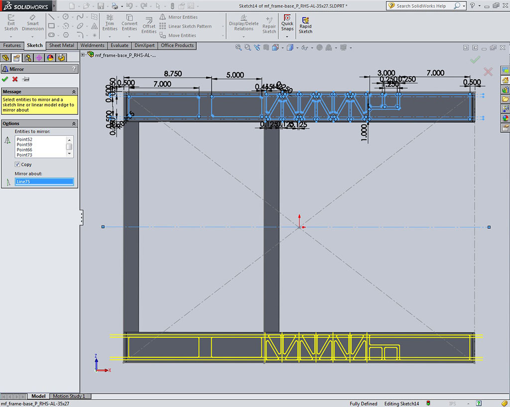
Sample 19
Mirror Cut
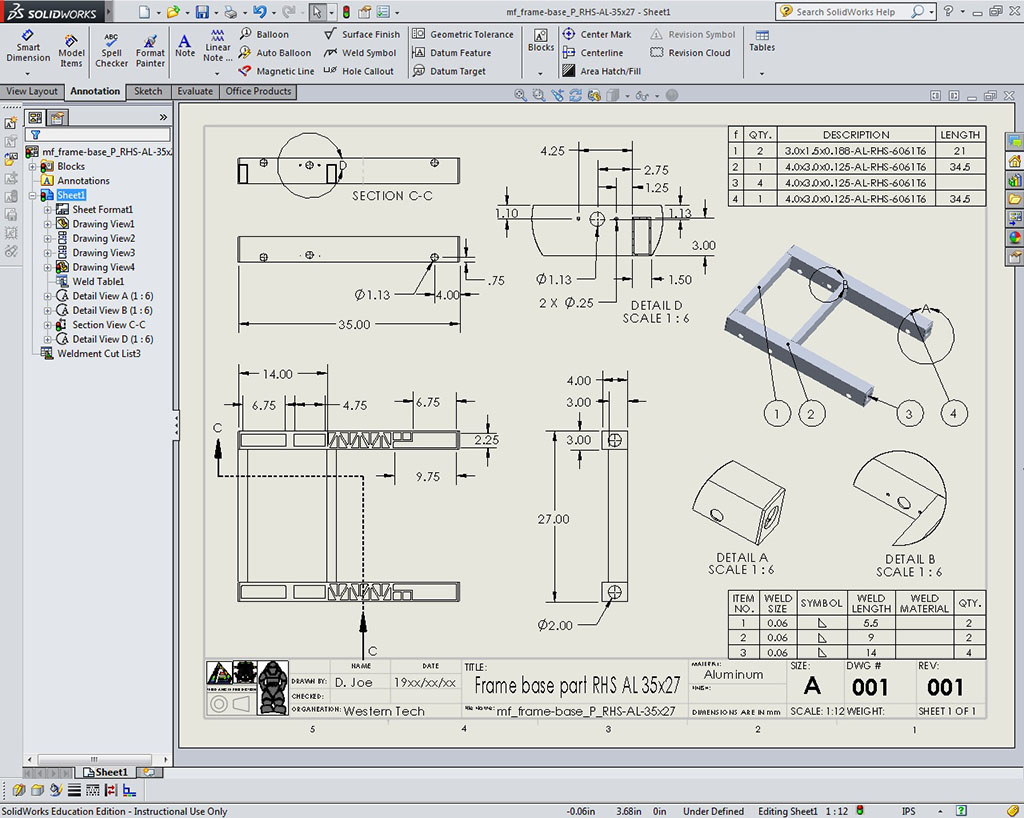
Sample 20
Drawing Example
Drawing
When model is complete, and you have rotated the model as a best isometric view, save the model and open up the custom drawing template. You will need to bring drawing views in, based on the three rules for selecting the front view. The views currently done are based on the final assembly. Therefore drag the appropriate view in from the view pallet for the actual front view, then project the top and right side views.
Keep in Mind
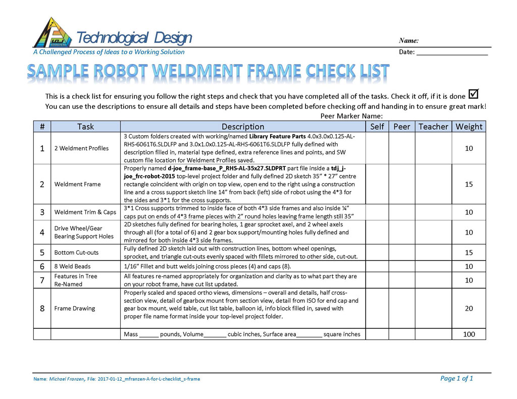
- dimension all major features - overall and detail
- remember not to put duplicate dimensions and space out properly
- detail on isometric the end cap and the gearbox mount holes - use detailing tool in command bar
- create a half cross section - accessed through sectional tool in command bar
- detail the half cross section gearbox mounting holes and dimension
- weld table based on ISO - right click on drawing view, select tables, then select weld table
- cut list table based on ISO - right click on drawing view, select tables, then select cut list table
- add balloon identification on ISO - right click on drawing view, select annotation, then select auto balloon and modify to suit
- fill in information block 3mm for regular lettering, 6mm bold for titles, size, drawing number and revision number
Hand in whole folder with correct folder and file naming conventions. Remember to include JPG's of both the model and drawing.
Custom Robot Frame

Using the sample frame process design already created, design a frame model based on your sketches of your custom frame design. A model and jpg file will be required for your final model custom frame. Using the supplied template, also create a drawing with dimensions and save as a jpg also to hand in. Again, make sure you create another separate folder to keep all your custom related robot design files: td3-1_d-joe_rob-custom with a frame file name td3-1_d-joe_rob-custom_P_desc-#x#.sldprt.
Evaluation:
Use the ![]() frame checklist with weights of importances to ensure you have completed all steps. Make sure your folders, files, organization, and naming conventions are saved correctly, files open up to appropriate views (for example model pat and/or assembly - full screen with best ISO view), all CAD files working (double check if you change file/folder names), and include full page JPG images of all CAD work. Remember when you hand in your SolidWorks project, make sure you have completed and handed in the SolidWorks Self/Peer Checklist sheet also. This self/peer evaluation sheet (worth 10% of project mark) is there to help you hand in the best product and get written feedback on your completed work.
frame checklist with weights of importances to ensure you have completed all steps. Make sure your folders, files, organization, and naming conventions are saved correctly, files open up to appropriate views (for example model pat and/or assembly - full screen with best ISO view), all CAD files working (double check if you change file/folder names), and include full page JPG images of all CAD work. Remember when you hand in your SolidWorks project, make sure you have completed and handed in the SolidWorks Self/Peer Checklist sheet also. This self/peer evaluation sheet (worth 10% of project mark) is there to help you hand in the best product and get written feedback on your completed work.
| Evaluation Breakdown Component Descriptions | Marks |
|---|---|
| Always double check that you have completed all components for full marks. | |
| Design Matrix - show 5 or more materials considered with total ratings | 20 |
| Frame Profiles - 2D sketches with appropriate references | 20 |
| Robot Frame - model and drawing | 50 |

Unit Conclusion
With the understanding to folders, files, and naming conventions with Solidworks will help with organizing and drawing in Solidworks. Learning basic and advanced CAD techniques with the toggle clamp leads into starting to build a robot frame using weldments, a very powerful tool in Solidworks. Being able to focus in one expert area and work/share with partners to help you with your design is very important in the engineering field. Knowing and practicing these skills, steps, and knowledge will empower your confidence in the design process steps and understanding, being able to communicate more with complex designs, and using Solidworks to create and show those ideas!