Unit 5: Grade 11/12 Technological Design - Robotics - Functions and Integration
This unit will continue with robot sample design build focusing on the rest of the functions including the tote intake grabber, recycling bin gripper, and the belly pan controls.
Course Units and Descriptions
Use this table for an overview and navigate to each of the course unit pages.
| Unit | Description |
|---|---|
| Review course outline for more details | |
| 1 | Careers & Safety- Intro, computers, organization, and research career |
| 2 | Engineering Communication- Technical sketching, ortho-ISO, custom ortho, and robot design |
| 3 | Structure and Materials- Materials & measurement, joints, frame, and 3D model |
| 4 | Driven Mechanisms- Gears, gearbox to wheel, drive train, and 1st function |
| 5 | Functions and Integration- Body base, pneumatics, 2nd and 3rd function |
| 6 | Robot Assembly- Robot build, function supports, drawings and presenting |
| 7 | Marketing and Portfolio- Web authoring, portfolio and presentation |
Unit Content Activity Quick Links, Click to Jump to Specific Activity!
 Unit 5, Act. 1: Tote Grabber Intake

Situation:
With the elevator part of the robot completed in Solidworks, the robot needs a way to collect or grab the totes from several locations on the game field, which will most likely be facing in different directions. Students already have the design process, ideas, concepts, calculations already done with final CAD model of mechanism done.
Problem/Challenge:
Students are to create the tote grabber intake mechanism. Students are to review how the design was created through idea generation, calculations, and prototypes to get to a finished idea and practice their CAD skills to create the same tote grabber intake mechanism. Assembly to be flexible where needed and have limitations to show operation of movement in model through the use of constraintes, mates, and planes.
Investigation/Ideas:
Design Idea Creation Process
Ideas or solutions to problems require an understanding of the design process (for example SPICE model) and how to apply it, related knowledge and experience. Looking at your resources, what you know in terms of the problem will give you a starting point. The following would have to be considered throughout the design process
- Game requirements, rules, how to get points, and limitations
- Understanding what the big picture is provides context and what the problem/challenge is in detail - having a clear understanding and vision on what has to be resolved
- Robot size, capacity, and tasks the robot must complete based on game points and your opinion on maximizing points
- Knowledge of mechanisms - mechanical association, motors - speed/torque, fastening, materials, etc
- Applying the priority of tasks into a method to complete them
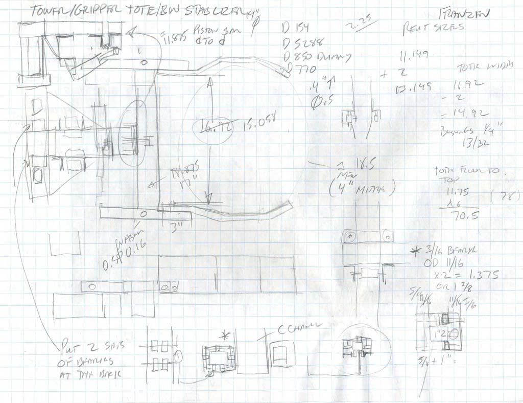
Below are some sketches and prototyping, showing some of this process. It is important to keep records of this process (documentation of rough notes, sketches, prototypes, researched information, design logs, etc., so that if you need to modify, update, or improve, you have somewhere you can continue from. Sometimes ideas that may not work for your intended goal, may have another use to a problem you may not have considered.
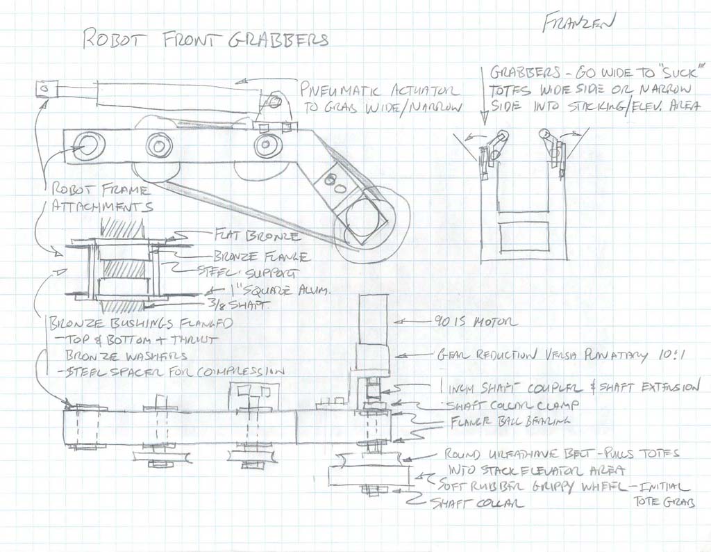
Tote Grabber
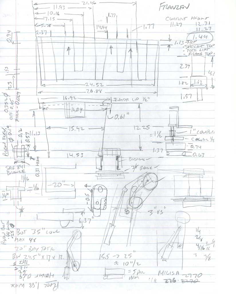
Calculations

Prototype 1
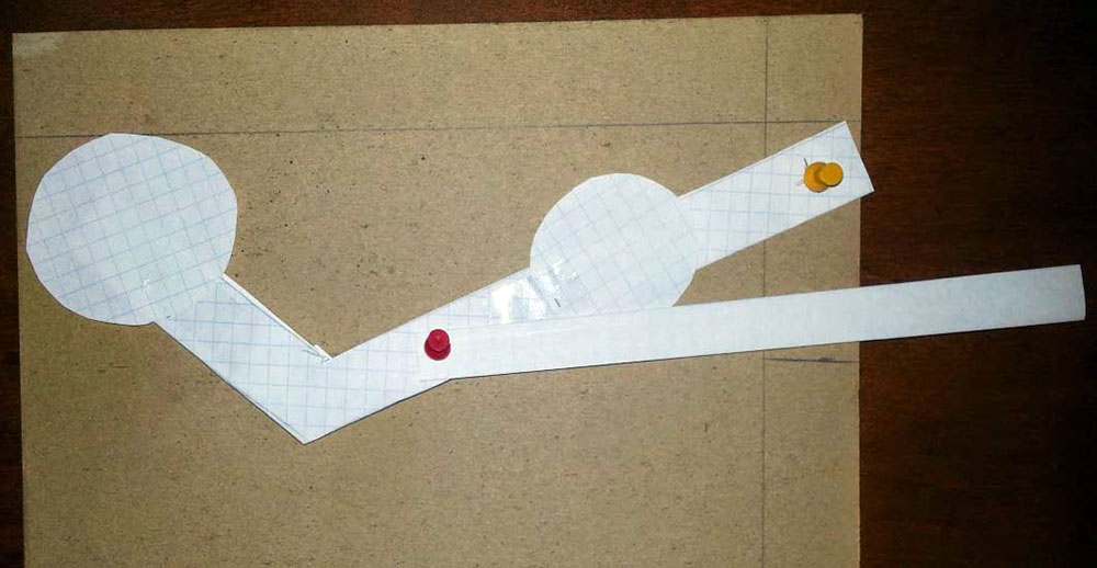
Prototype 1
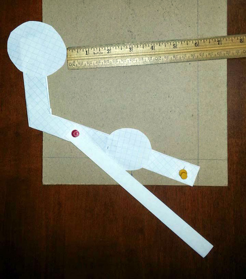
Prototype 1
Having already experienced some CAD with this complex robot design, will allow you to focus on building more experience with CAD, but keep in mind that the idea, where it all starts, and how you take that idea to a working solution that is important. For this reason, seeing and understanding a process path of how the Tote Grabber Intake was developed, will allow you to apply this to other problems/challenges.
The following topics should be reviewed for preparation for this CAD build:
- CAD, Engineering, sizing, material standards
- Adding materials, properties, and appearances
- Using the toolbox for fasteners
- Fixed vs flexible assemblies
- Belt/chain tool
Resource Links
Below are some resource links related to the tote intake grabber:
Create/Construct:

Tote Grabber Intake CAD Build Steps
This tote grabber intake assembly is made up of some custom parts you will have to create. The motor with gear box, bane-bot wheel, and Bimba pneumatic piston are already made and you should find them in the school class library network share.
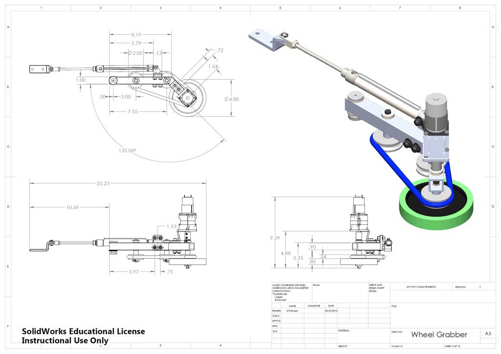
Remember to use the related eDrawing file found in your school class folder to see assembly and part details. Manufactured parts used should be in the school networked share CAD folder library. Below are the basic steps to complete the robot grabber system. Note the weldment profile: square hollow section (SHS) profile: 1.0x1.1x0.125-AL-SHS-6061T6.SLDLFP is already made. Use folder/file use and naming conventions, name features in feature tree, add the summary information, properties, and material for each custom part made.
- Create the motor mount bracket
- Create the clevis support bracket
- Using your square hollow section (SHS) profile: 1.0x1.1x0.125-AL-SHS-6061T6.SLDLFP profile, create the frame of the grabber, note when originally made, mounting holes for brackets were made using the "Convert Entities" tool
- There is a spacer, hex shafts, brass thrust bushings, and pneumatic base bracket also to be custom made
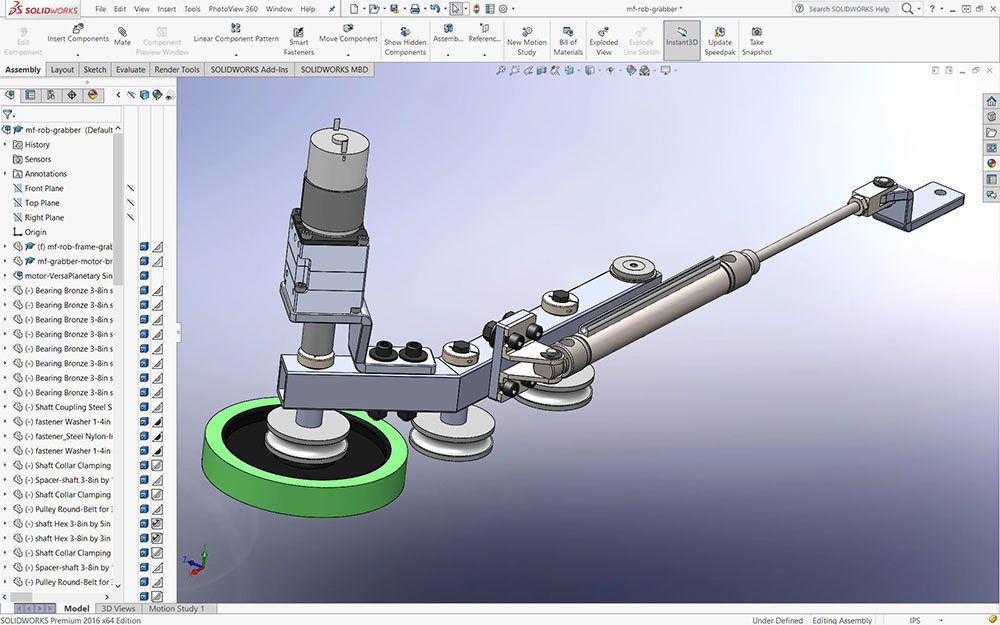
- Start assembly using the frame first, then bring in the motor mount, motor, hex shaft coupling, shaft collar, brass thrust bushings, shaft spacer, pulley, bane-bot wheel, and another shaft collar
- Next add to the assembly the two other pulleys with their shaft, spacers, brass bushings, shaft collars
- End elbow joint that will be attaching to robot frame will need to be made, which has some custom washers, brass thrust bushings
- Last major part to attach, is the pneumatic piston (recognize and bring in flexible) with the custom piston base, and the piston clevis support bracket.
- In order to get the assembly to move the way it is suppose to, you will need to fix the piston clevis support bracket and the arm axis as what will be on the robot drive base.
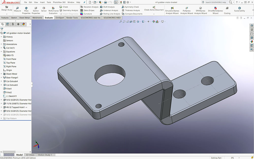
Motor Mount
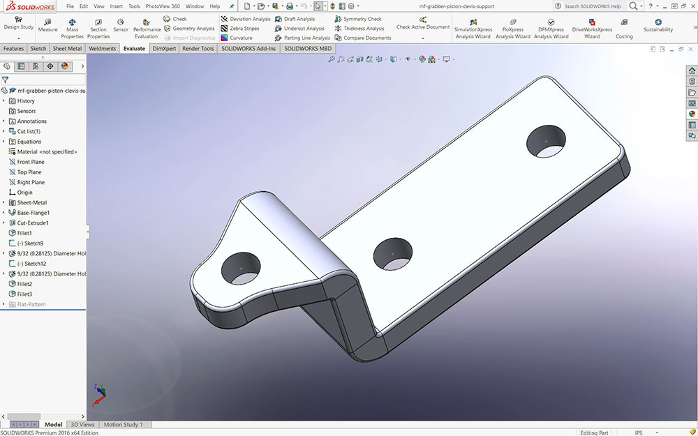
Clevis Support
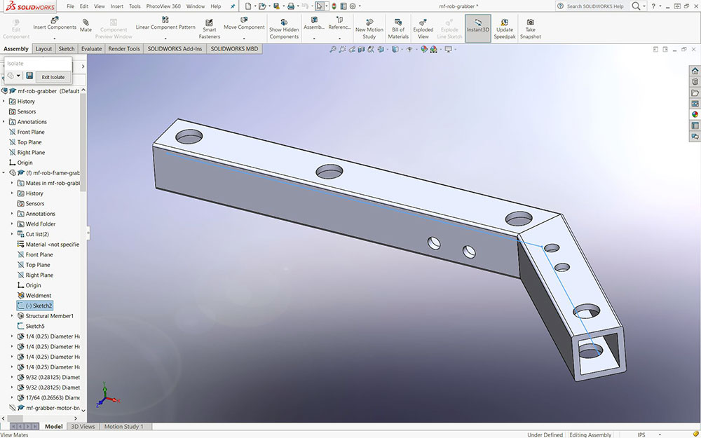
Grabber Frame

Motor Drive

Pulleys
Piston
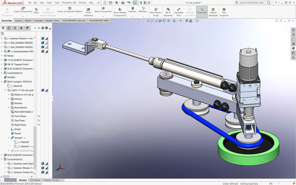
Round Belt
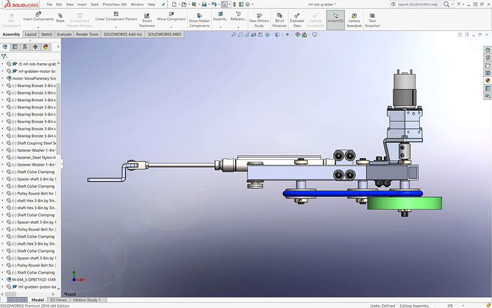
Front View
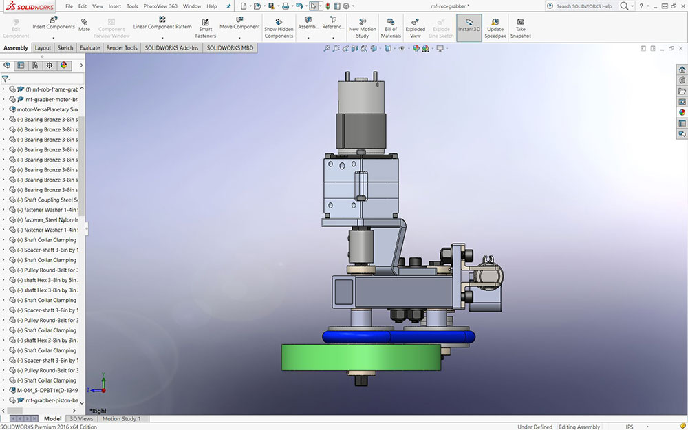
Side view
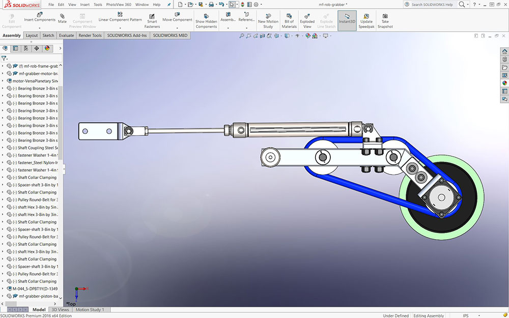
Top View
Evaluation:

You are responsible to hand in your sub-assembly as a separate folder for evaluation, master assembly will be looked at in Unit 6.
Make sure your folders, files, organization, and naming conventions are saved correctly, files open up to appropriate views (for example model part and/or assembly - full screen with best ISO view), all CAD files working (double check if you change file/folder names), and include full page JPG images of all CAD work. Remember when you hand in your SolidWorks project, make sure you have completed and handed in the SolidWorks Self/Peer Checklist sheet also. This self/peer evaluation sheet (worth 10% of project mark) is there to help you hand in the best product showing your process build and get written feedback on your completed.

| Evaluation Breakdown Component Descriptions | Marks |
|---|---|
| Always double check that you have completed all components for full marks. | |
| Tote Grabber Intake - Working Assembly showing movement and limits | 50 |
Unit 5, Act. 2: Recycle Gripper
Situation:

Students are gaining a lot of experience with Solidworks and reviewing the design process steps in detail. With the tote grabber intake complete, the robot functions are nearing completion and the robot design is getting closer to it's finish. It is really important to be able to collect those totes, but there are other things that can be done to get extra points. It is these extra points that will gain advantage over other teams. More functions can add more abilities to the robot, thereby gaining more points, but it also needs to be said, too many functions can over complicate the operation and possibles of something going wrong with your robot.
Problem/Challenge:
Students are to create the recycling bin gripper mechanism function to be able to grip the recycling bin from different configurations and hold on top of tote stack collected. To start, students are to review how the design was created through idea generation, calculations, and sketching ideas to get to a finished idea and continue to practice their CAD skills, to create the same recycling bin gripper mechanism. Assembly to be flexible where needed and have limitations to show operation of movement in model through the use of constraints, mates, and planes.

Design Creation
Looking at points, getting the bin on top of your stack with a noodle, gave you a advantage on points if you can get a tote stack with 4 points per tote bonus and the litter can also add another 6 points. So with maximum height of robot, 6 stack tote (2 points each) + recycle bin (4 points * 6)+ noodle litter (6 points) giving you 42 points, of which just two of those items namely the recycle bin and the noodle litter making up 30 of those points. Now that we have the importance of the recycling bin, how do we get it.
You have to take into account that the bin will most likely be on its side, but also possibly standing up, so for that reason the gripper shape was designed around both possible shapes. It was also design to be able to grip horizontally or vertically to allow for flexibility in getting those bins.
- Bins could be any configuration
- Bins gripper must be able to grip and hold bin in place while elevator lifts totes up after tote grabber intake pulls the totes in
- Gripper must be able to grip horizontally and vertically
- Gripper must be able to hold the bin throughout the stacking process to keep bin stabilized on top
Gripper

Gripper
Sheet Metal Tool Review
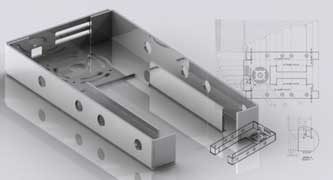
As you will be using the sheet metal tool in Solidworks to create two parts here, a review of how the tool works is called for. This tool is very handy allowing you to make sheet metal type characteristic parts. In industry if you think about it, sheet metal is used in a lot of products and then you will realize why CAD programs include this as a tool to efficiently create/design these type of parts. Everything from your kitchen appliances to cars use sheet metal.
A great introduction to sheet metal with SolidWorks should be reviewed. Being aware of the different characteristics of sheet metal, its manufacturing process, and advantages of using it, you will be able to design some effective and practical designs.
Sheet Metal in SolidWorks
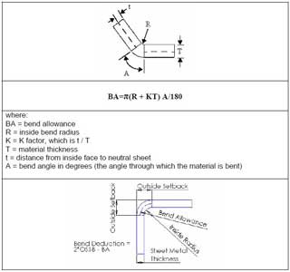
The Sheet Metal feature tools in SolidWorks, works with the basic characteristics of a thickness gauge of flat material with the ability to make and control bends. SolidWorks has built in gauge tables for thicknesses for different materials and your own custom tables can also be added. Bends tables are also provided to automatically calculate the standard bend radius and bend allowance based on material, thickness, bend radii, and bend angles, but custom bend tables can also be added.
When edges are bent, spacing and relief cuts with different shape options need to be considered. The spacing may be for clearance for the bend itself or you may want a gap for a weld to support and strengthen the design. A powerful option that SolidWorks offers, is to flatten your design so that the manufacture can cut out the pattern. Once the pattern is cut out, there may be additional holes, cut-outs, miters, and press forming prior to the bending, which may include simple straight bends, edge flanges, corner treatment, hems, rolls, lofts.
Key Terms
The following are some common sheet metal feature tools that could be used with your design creation.
- Base Flange - creates sheet metal part from both open and closed sketches
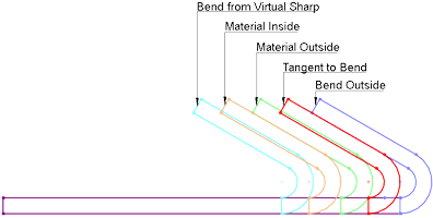
- Edge Flange - adds a flange that extends from existing model edge with alignment options Material Inside, Outside, and Bend Outside and relief cuts Tear, Rectangular, and Obround
- Mitre Flange - similar to Edge Flange, but are made with a cross section open sketch and will automatically mitre corners
- Hems - simple feature to strengthen edges created with a number of parameters in the property manager
- Swept Flange - open profile perpendicular to a custom pathway of lines and/or arcs to create a sheet metal part
- Forming Tool - is a mould to re-use through your SW Design Library to create unflattened features/shapes on your sheet metal part
- Sketched Bends - allows you to draw a line on a flat closed profile and bend it on that line and should be careful with alignment options
- Flatten - see your folded design in flattened state and be aware that flattened operations do not propagate back to the formed state
- Unfold/Fold - if you need to complete edits or operations, use this tool rather than the flatten tool, so that
- Rip & Insert Bends - starting with thin geometry based on extrudes and shells, you can manually convert to sheet metal with bend locations and rip or separation sections
- Lofted Bends - using two open 2D open profiles, create a smooth transition from one shape to the other

Resource Links
The following support links are great resources on sheet metal (SM) tools and related information for use with SolidWorks (SW).

 Sheet Design
 Intro to SW Sheet Metal
 SW Intro and Capabilities
- Introduction to SM, Play list
- SM Design in SW
- SW Help on SM
- SM Design e-Book
- GoEng - SM tools 1
- GoEng - SM tools 2
Create/Construct:
Recycle Bin Gripper Mechanism
Design steps start with the gripper arms to be made out of sheet metal using Solidworks sheet metal tool. Using a large diameter construction circle for the size of the recycle bin before the neck, to get a reasonable grip. The shoulder (we'll call it that because it holds the gripper arms that attaches to the track body) will support the gripper arms ablity to move in and out in a horizontal and vertical angle thereby being able to grip the recycling bin either standing up or laying down.
Remember to use the related eDrawing file found in your school class folder to see assembly and part details. Manufactured parts used should be in the school networked share CAD folder library. Below are the basic steps to complete the tote gripper module. Note the weldment profile: square hollow section (SHS) profile: 1.0x1.1x0.125-AL-SHS-6061T6.SLDLFP is already made. Use folder/file use and naming conventions, name features in feature tree, add the summary information, properties, and material for each custom part made.
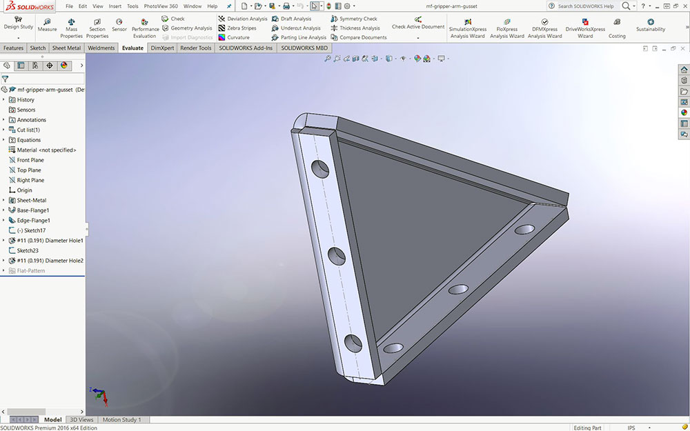
- Create a construction circle 15.058" with a centre construction line, another line tangent to the outside of the circle, and another 2 construction lines perpendicular 1.721 from the edges of the circle, then use the sheet metal tool to create the arm flat following the circle shape, then bend outside edges to create strength
- Create some small angle brackets to hold/support those angle on the edges attaching with rivets (not shown in tutorial pict, but you can see them in picture at the beginng of the unit activity).
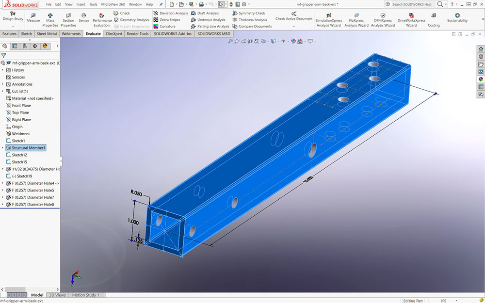
- The rest of the frame parts for the shoulder are made using the weldement tool with profiles starting with the cross piece to keep the gripper arms spaced out
- Create the RHS square arms for the grippers, which will also hold the tote stablizer plates
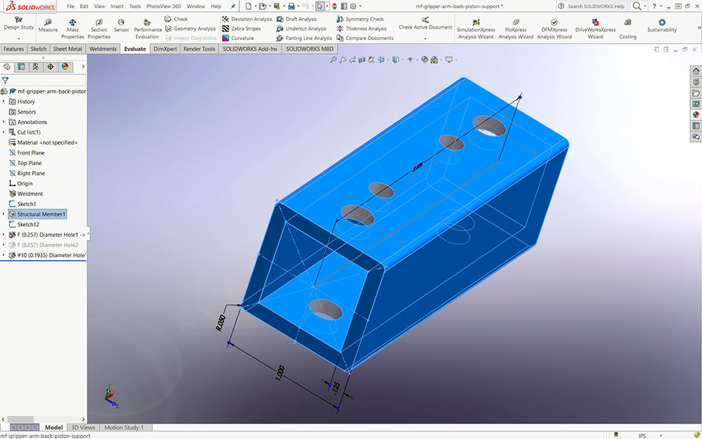
- Create the back of the arms house this spacer, used to control the gripper arm action. This spacer is needed to clear the ninty degree angle support for piston and angle cross bar.
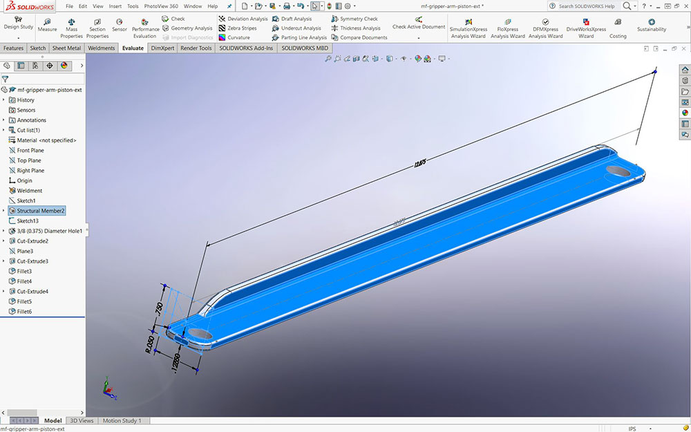
- Create the angle aluminum piece for the cross support extension for the piston that controls the gripper arm action
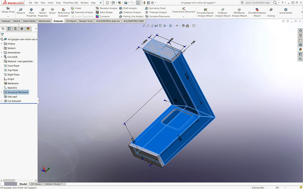
- Create the shoulder angle to support the gripper arms throught the main cross piece
- Using the sheet metal tool again, make a angle support to support the sholder angle
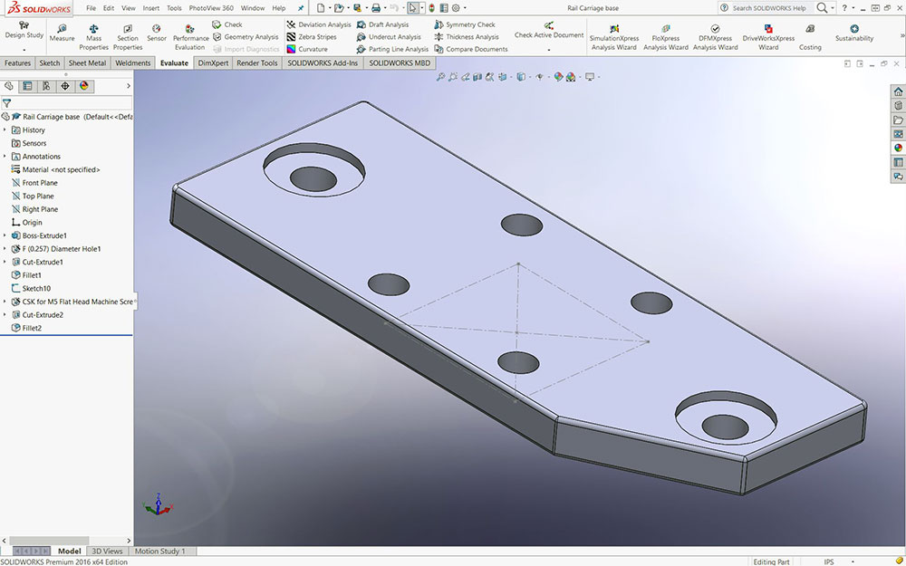
- Rail base support base plate is needed to be made to support the rail carriage
- The rail carriage is a manufactured part
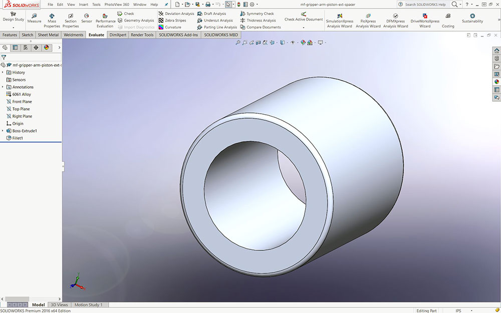
- Spacaer will need to be made for piston extension arm alignment
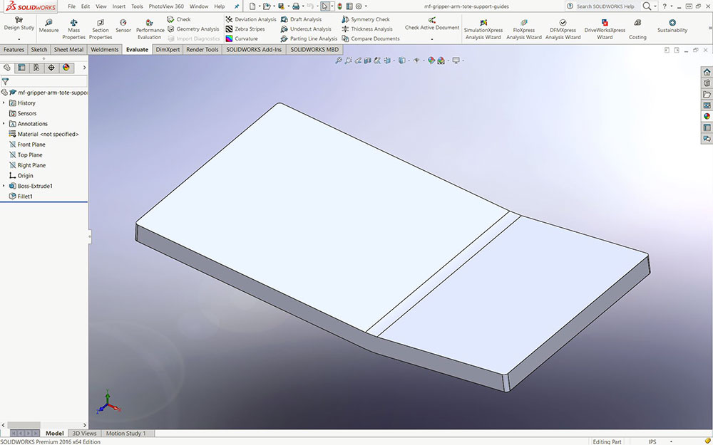
- the tote plate will hold the top tote from falling, i.e. stablize you stack while holding the gripper holds the recycling bin - dual purpose
- Hinge created to be used to allow for that ninty degree action for the gripper. This one was made but you may be able to find a standard sized one to use here. Pin must be capped from both ends permamently
- This is one of two pistons you will need to bring in. Remember that these will have to be made flexible and then mated with limits to get it working with virtual action
- Once you have all your parts, you can start to put all togerher using appropriate mate
Steps to Build Gripper

1 gripper

2 Gripper

3 Cross Arm
4 Arm
5 Spacer
6 Piston Ext.
7 Sholder
8 Support
9 Rail Base

10 Carriage
11 Spacer
12 Tote Plate
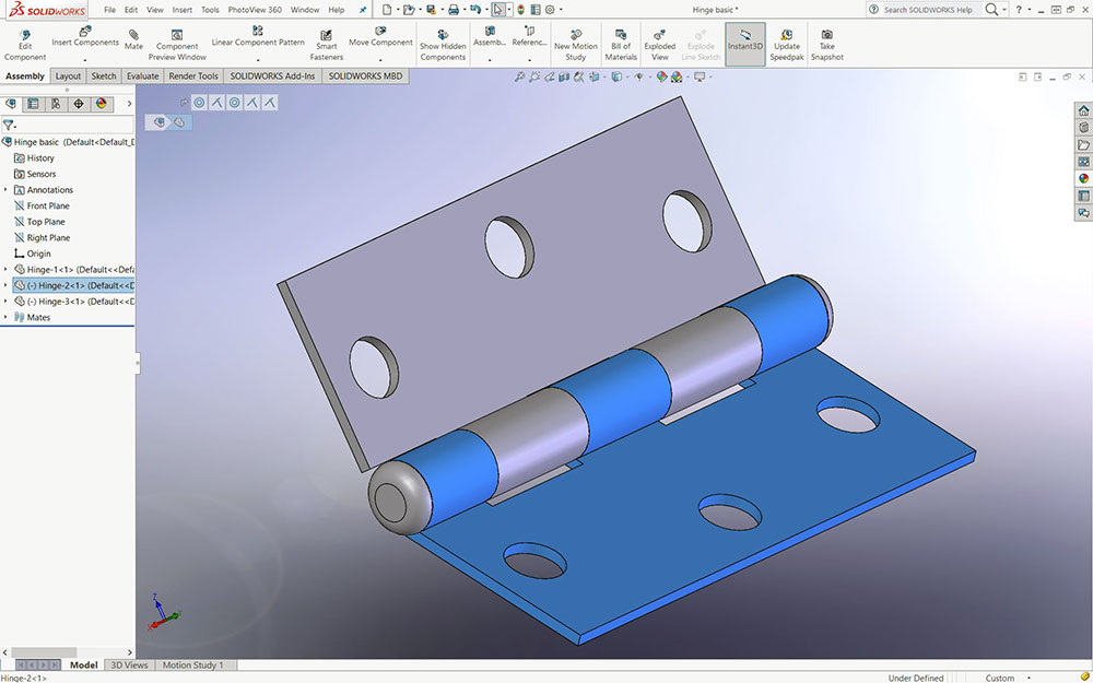
13 Hinge
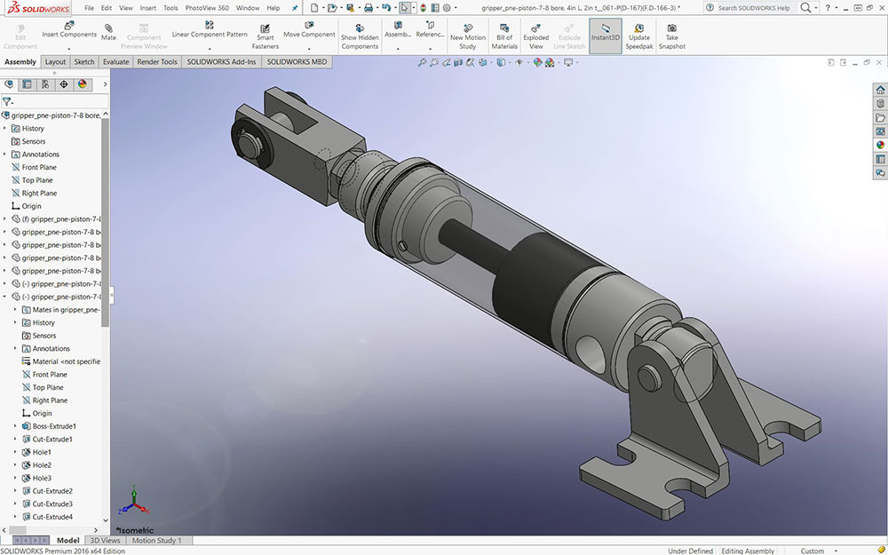
14 Piston
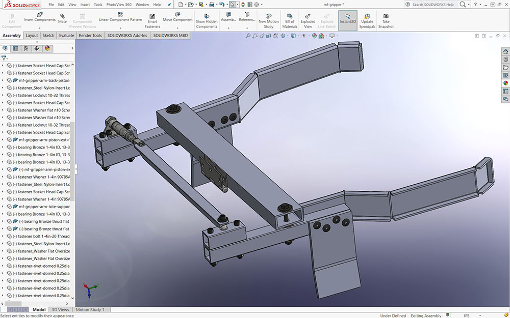
15 Assembly
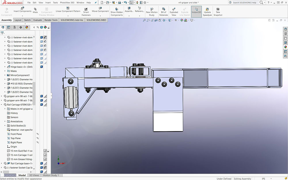
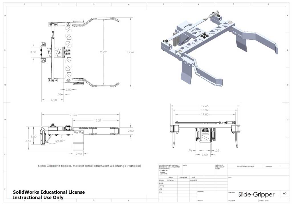
Front View
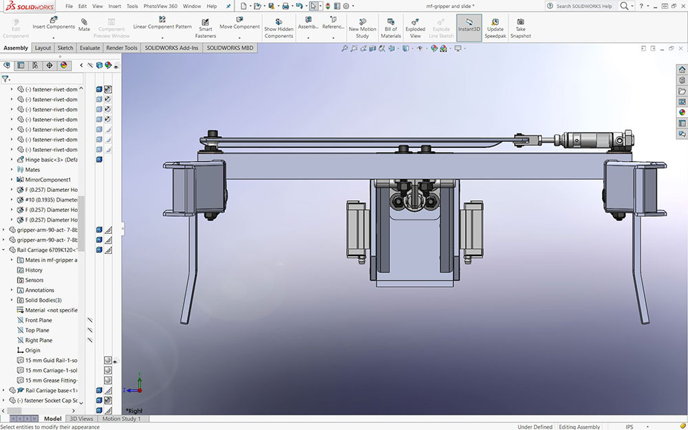
Side View
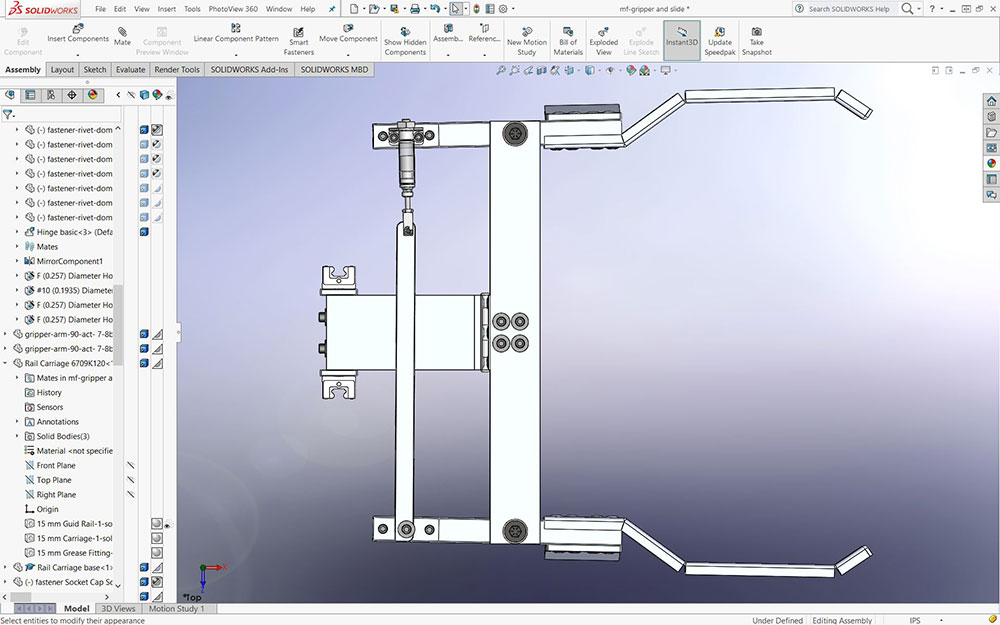
Top View
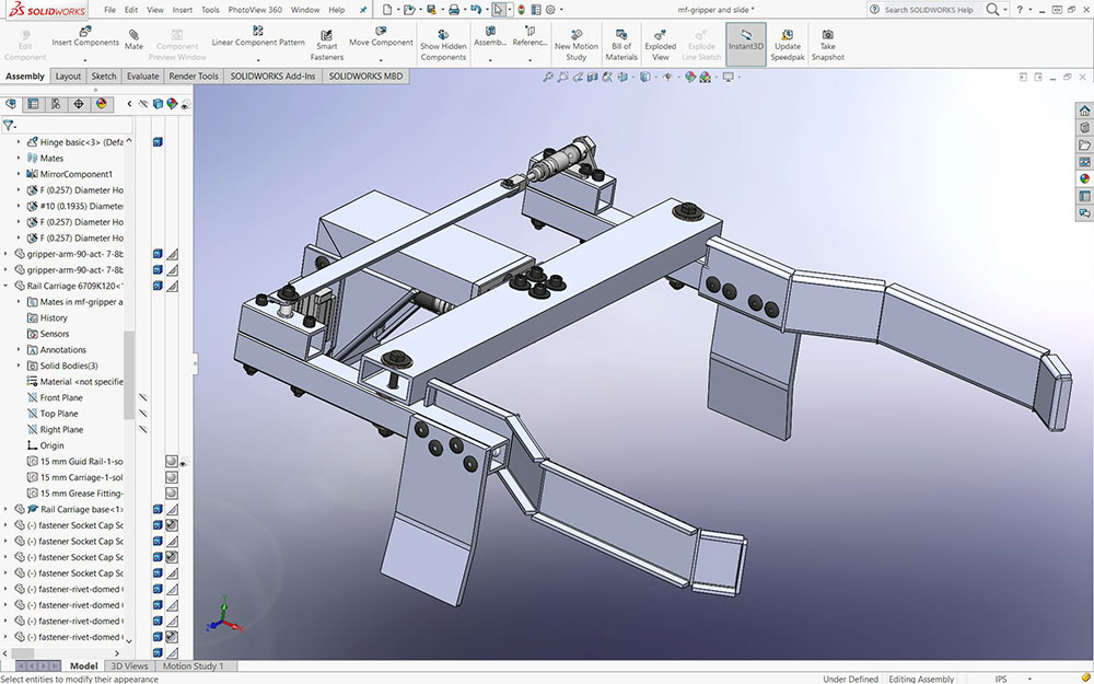
ISO View
Gripper Completed
Evaluation:

You are responsible to hand in your sub-assembly as a separate folder for evaluation, master assembly will be looked at in Unit 6.
Make sure your folders, files, organization, and naming conventions are saved correctly, files open up to appropriate views (for example model part and/or assembly - full screen with best ISO view), all CAD files working (double check if you change file/folder names), and include full page JPG images of all CAD work. Remember when you hand in your SolidWorks project, make sure you have completed and handed in the SolidWorks Self/Peer Checklist sheet also. This self/peer evaluation sheet (worth 10% of project mark) is there to help you hand in the best product showing your process build and get written feedback on your completed.
| Evaluation Breakdown Component Descriptions | Marks |
|---|---|
| Always double check that you have completed all components for full marks. | |
| Recycle Gripper-Working Assembly showing movement and limits | 70 |