
Unit 3: Computer Engineering Technology:
Digital Logic & Circuits
This unit will focus on computer evolution introducing number systems, binary, octal, hexadecimal, boolean, logic gates, counters/register ccts., design, build and operation.
Course Units and Descriptions
Use this table for an overview and navigate to each of the course unit pages.
| Unit | Description |
|---|---|
| Review course outline for more details | |
| 1 | Safety & Career - Intro, computers, organization, safety, careers, and custom proposal |
| 2 | Computers & Components - Electronics, operation, design, troubleshooting, and maintenance |
| 3 | Digital Logic & Circuits - Binary, boolean, logic gates, counters/register ccts., calculations, design, & build |
| 4 | Networking & Programming - IP addressing, data routing protocols, services, languages, and concepts |
| 5 | Hardware Interface & Control - Student designed custom project |
| 6 | Showcase & Web Portfolio - Testing and presentation |

Unit Content Activity Quick Links, Click to Jump to Specific Activity!
- Unit 3, Act. 1: Computer Evolution and Numbering Systems
- Evolution, Number Sys, BCD, Conversions, Dec to Bin, Oct to Hex, Conversion, Work Sheets, Bin Cal, Bin Add, Bin Sub, Resources, Steps, Eval
- Unit 3, Act. 2: Circuit Characteristics and Calculations
- Unit 3, Act. 3: Logic Gates
- Unit 3, Act. 4: Design, Build, and Analyze Digital Logic Circuits
 Unit 3, Act. 1: Computer Evolution and Numbering Systems
Situation:
A big part of computer technology is looking at its development, current operation, how it works with data.


Problem/Challenge:
Students will look at the evolution of computers and how it relates to today's current systems and their future then answer review questions on this topic.
Students will also review numbering systems: Decimal, Binary, Octal, and Hexadecimal and practice conversions, binary addition, and subtraction to understand how a computer works with data. Review questions including general questions, conversion problems, and some addition/subtraction binary problems.
We will also continue to finish working on computer service, maintenance, and troubleshooting then start working on the Raspberry Pi beginner project using the task tracking sheet.
Investigation/Ideas:

Computer Evolution
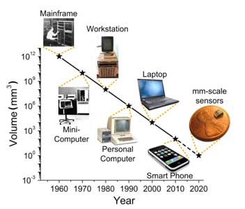
The digital computer is a big part of our lives. Looking at the ![]() evolution of the computer, the different stages developed by five significant technological jumps leading to higher level of computing, you can better understand, how the computer came to be. The following is a quick summary of the five major generations of the computer:
evolution of the computer, the different stages developed by five significant technological jumps leading to higher level of computing, you can better understand, how the computer came to be. The following is a quick summary of the five major generations of the computer:
- 1940 1956: First Generation Vacuum Tubes
- 1956 1963: Second Generation Transistors
- 1964 1971: Third Generation Integrated Circuits
- 1972 2010: Fourth Generation Microprocessors
- 2011 - Current: Fifth Generation Artificial Intelligence

Related Links
 The digital computer
 Evolution of the computer
 Evolution, 30s
- Computer revolution time-line
 Early Computing, 11.52
- Electronic Computing, 10:43
- Birth of the computer
- UNIVAC and ENIAC Computers
- Memory and storage
- Drum memory and Magnetic-core memory
- Vacuum tubes and Transistors
- Punch Cards
Number Systems - Decimal, Binary, Octal, and Hexadecimal
There are 10 types of people in this world. Those who do understand binary and those who don't. (A little digital humor, did you get it?)
Computers communicate or move data using 1's and O's. This binary data forms the basis of all computer and digital data systems such as your transistors in CPU, cat5 cable and/or WiFi signals, or any other digital data commonly used today.
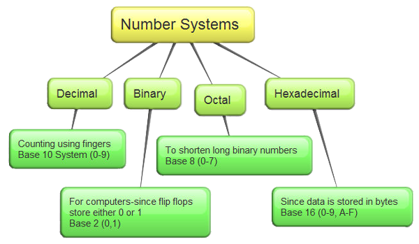
There are four main numbering systems used in the human, networking, and computer world; decimal, binary, Octal, and hexadecimal. The decimal numbering system which we know and use regularly is a base 10 with numbers 0 to 9 to represent a decimal number value.
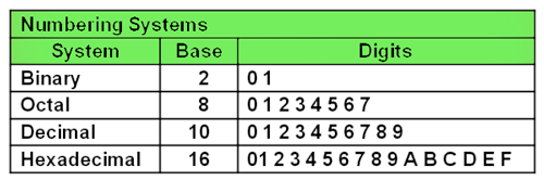
Table 1: Digit Representation
Binary numbering system has a base 2 and uses 1's and 0's because digital is either a high/on or a low/off. Octal has a base of 8 and uses 8 digits between 0 and 7, Hexadecimal has a base of 16 using a total of 16 numeric and alphabetic characters to represent a number value (0-9 and A-F).

Eight-Bit Binary Counter
Application of BCD (Binary Coded Decimal) - Display
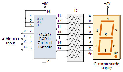
![]() Binary Coded Decimal (BCD) system has the advantage of being fast and efficient to convert decimal numbers into binary as compared to the pure binary system. Each decimal digit (0-9) is represented by a group of four bits(not to be confused with hexadecimal). The main disadvantage is it's wasteful states between 1010 (decimal 10), and 1111 (decimal 15) are not used, but BCD have many important applications such as digital displays.
Binary Coded Decimal (BCD) system has the advantage of being fast and efficient to convert decimal numbers into binary as compared to the pure binary system. Each decimal digit (0-9) is represented by a group of four bits(not to be confused with hexadecimal). The main disadvantage is it's wasteful states between 1010 (decimal 10), and 1111 (decimal 15) are not used, but BCD have many important applications such as digital displays.
A byte is defined as a group of 8 bits. Typically a group of four bits is referred to as a nibble. Words are larger groups of bits, with some common value examples; 16, 32, and 64-bit words. On a side note a more specific reference for different sized words are; WORD (16 bits/2 bytes), DWORD (32 bits/4 bytes), and QWORD (64 bits/8 bytes) respectively, although there is no absolute set definition. Hexadecimal numbers neatly break down into one byte, or two nibbles, while octal numbers do not. As a result of this, the hexadecimal number system has recently become more popular in computers and programming. Hexadecimal numbering system uses only four digits to express a single 16-bit word length, resulting as the most commonly used base numbering system for computer systems.
 Is a Kilobyte 1000 Or 1024 Bytes? As for bit/byte number representation, if based on binary, kibi- is Ki: 1 KiB (kibibyte) = 210 bytes = 1024 bytes, so 1MiB = 1024 kilobytes, 1 GiB = 1024 megabytes, 1 TiB = 1024 gigabytes,
where as the SI kilo- is k: 1 kB (kilobyte) = 103 bytes = 1000 bytes, so 1MB = 1000 kilobytes, 1 GB = 1000 megabytes, 1 TB = 1000 gigabytes,
...So just be aware of the differences of both! More on kilobyte here!
Number System Conversions

Binary to decimal (radix or base 2 to base 10) and vice/versa, conversions are needed because working with very long binary numbers are hard to read/write and therefore commonly converted. Understanding the conversion methods also helps with understanding how and why data is used in this form. Not to worry, there are a lot of online calculators to convert, add, subtract, etc., knowing this process gives a better understanding of number systems and their relations. There are several examples in detail, in the resource links provided below, but a quick explanation is below for converting from Binary to Decimal and Decimal to Binary below.
Binary to Decimal
Binary to decimal is pretty simple, just take the binary data, place a decimal column value above each, then add up the values where a high/one is located:
Decimal value row: 128 64 32 16 8 4 2 1 (maximum value = 255, 1 byte or 8 bits)
Sample 1: 0 0 1 1 0 0 1 1 which is 32 + 16 + 2 + 1 = 51
Sample 2: 0 1 1 0 0 1 1 1 which is 64 + 32 + 4 + 2 = 103
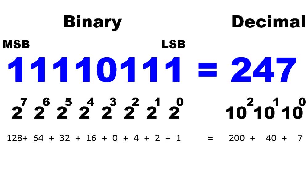
If you find a binary number smaller than a byte, such as 11000 (24 decimal) just pad the missing 0's to to complete an official byte (00011000) and if you come across a larger number just increase your decimal value column by doubling the previous column decimal value, i.e. 128*2= 256, 256*2= 512, etc then use those values to convert. One last thing LSB = least significant bit, while MSB = most significant bit, which are commonly used when talking about binary numbers in general.
Decimal to Binary
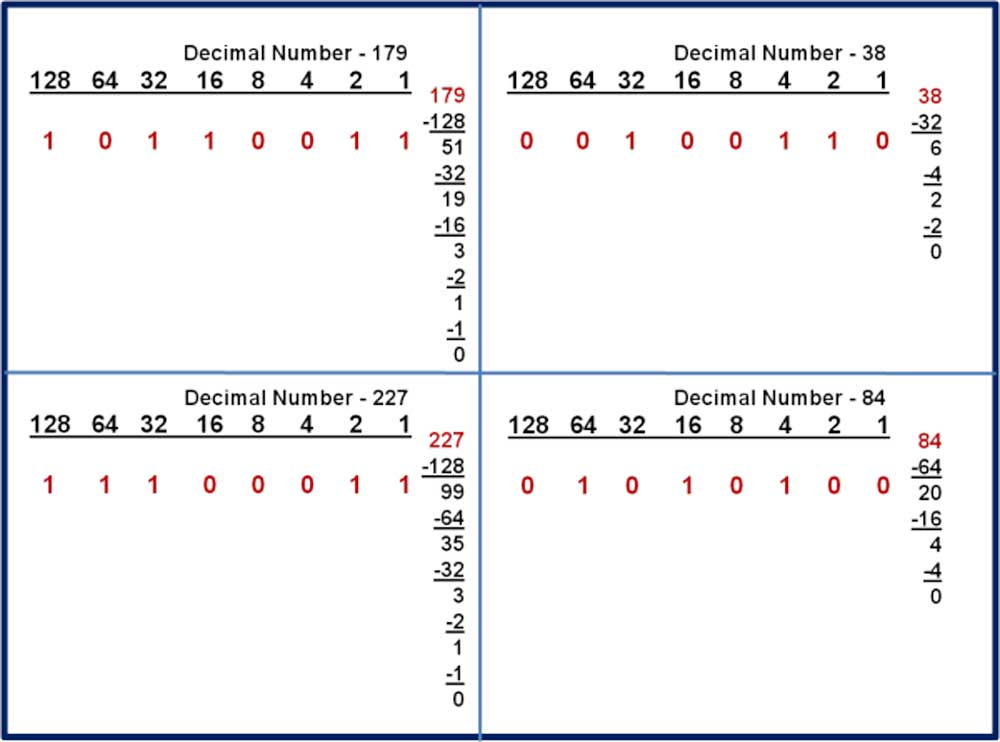
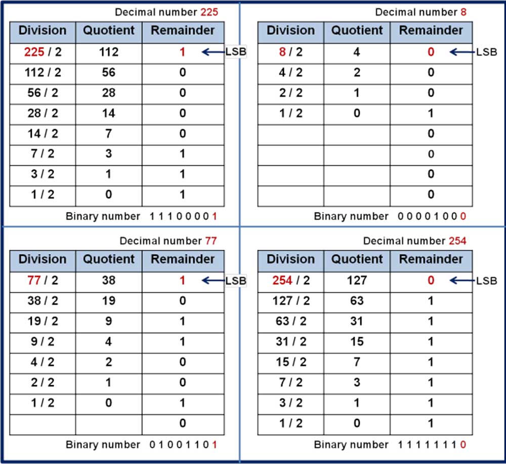
There are methods that can be used, the process of elimination or the divide and conquer methods. Working with a byte size (maximum decimal value of 255 which is 11111111 or 128+64+32+16+8+4+2+1=255), the process of elimination method, by comparing the decimal number with the MSB (128). If your number is larger than or equal to 128 then place a 1 under the 128 column, subtract 128 from your number and move to the next position (64). However, if your number is less than 128 then place a 0 under the 128 column and move to the next number (64) without subtracting. A second method, divide and conquer, you just divide your decimal number by 2, with the remainder used as your LSB, 1 or a 0, then continue to divide and repeat.
Elimination Method Samples
Divide/Conquer Method Samples
Octal and Hexadecimal
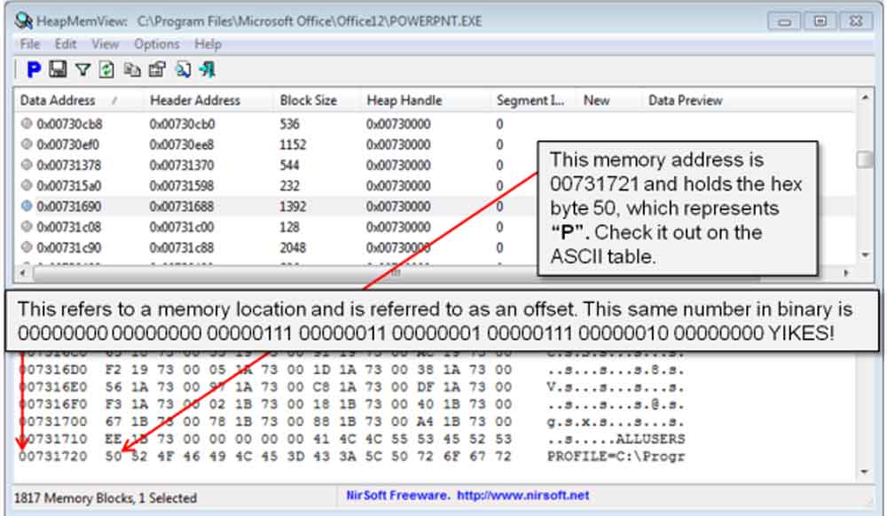
Oct for short is a numbering system that represents 0-7 while Hex for short, is an efficient numbering system widely used in to represent 1's and 0's in the computer data world. Hex could represent colours, memory, IPv6 and MAC addresses as examples. A sample memory dump image to the right shows an example of hex numbering system being used. As you know a binary byte is 8 digits, but a hex byte number is only 2 digits in length where a decimal byte (1-255) can be 1 or 3 digits long. Additionally, an ASCII Code table can be referenced to find out what each of the characters represent. Remember hex represents 0-9, A-F (0-15 in decimal), so for example 0xF + 0x1 = 0x10, or 0xF + 0x2 = 0x11, where the Ox (Hash # and/or dollar sign $ also may be used) is common to represent actual hex, so you can't mix it up with binary digits. So 11 binary is decimal 3, but 0x11 in hex is decimal 17. A sub-script can also be used to represent either oct8 or hex16 also.
Converting Octal and Hexadecimal
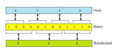
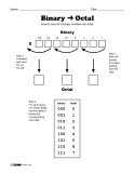
To convert binary to octal start at the binary point and work left separating bits into groups of three. You may need to pad some leading zeros to the MSB of the binary number to complete the last group, which does not change the value of the number. If a binary number contains digits to the right of the binary point, they can also be converted by starting at the binary point and working right while also separating them into groups of three. Once all bits are grouped, then replace the groups with the proper octal digit:
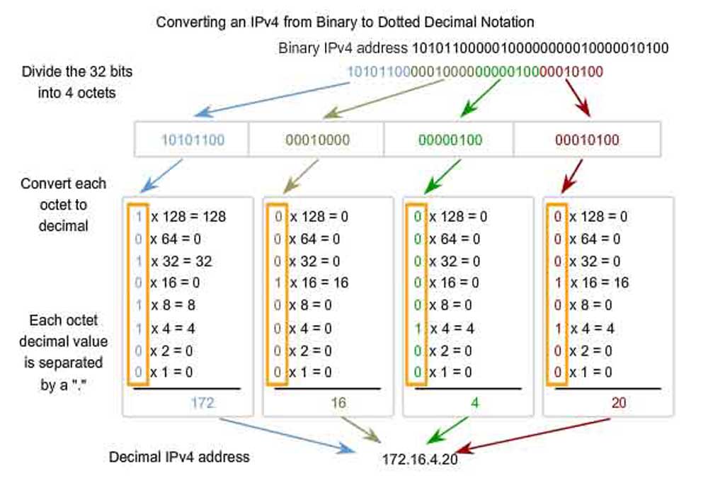
Sample binary to decimal IPv4 Internet address, IPv4 vs IPv6
10101100102 = 001 010 110 0102 = 12628
101110.01012 = 101 100. 010 1102 = 54.268
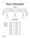
Converting binary to hexadecimal is similar, except you use groups of four bits:
101111101012 = 0101 1111 01012 = 5F516
11011010.0001000012 = 1101 1010. 0001 0000 10002 = DA.10816
![]() Remember that we add leading zeros if we need them to fill out the groups of three or four.
Remember that we add leading zeros if we need them to fill out the groups of three or four.
To convert from octal or hexadecimal back to binary you just need to replace each octal or hexadecimal digit with the corresponding 3 - or 4 - bit string, shown below:
15428 = 001 101 100 0102
3535.438 = 011 101 011 101. 100 0112
CD9516 = 1100 1101 1001 01012
E39A.8A16 = 1110 0011 1001 1010. 1000 10102
Number Systems - Converting Work Sheets
The following work sheets can be used for review or practice in converting between binary, octal, decimal and hexadecimal number systems.
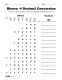
Converting from binary to decimalWorksheet showing how to convert from binary to decimal. |
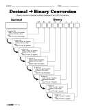
Converting from decimal to binaryWorksheet showing how to convert from decimal to binary. |
Converting from binary to octalWorksheet showing how to convert from binary to octal. |
Converting from binary to hexadecimalWorksheet showing how to convert from binary to hexadecimal. |
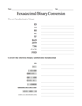
Converting between binary and hexadecimalWorksheet to practice converting between binary and hexadecimal. |
Binary Arithmetic
Addition and subtraction of non-decimal numbers is very similar to decimal numbers, except you use different bases. Instead of using base 10 in decimal form you are use to, you use base 2 in binary form. In addition carries are used while in subtraction borrows are used to get through the process. When you finish doing your manual calculation, convert to decimal to double check. Below are a couple examples of each process.
Binary Addition

Addition with binary, you start from the right and work to the left, adding each column and including the carry out from each column to the next column’s sum. When you have binary points, it works the same.
The following binary addition rules should be kept in mind when adding:
- 0 + 0 = 0
- 0 + 1 = 1
- 1 + 0 = 1
- 1 + 1 = 0, and carry 1 to the next more significant bit
- 1 + 1 + 1 = 1, and carry 1 to the next more significant bit...
Decimal and Sample Binary Addition 1
Decimal and Sample Binary Addition 2
Binary Subtraction

Subtraction with binary is similar, but uses borrows instead of carries between steps. The larger number/value is put on top and smaller number is
The following binary subtraction rules should be kept in mind when subtracting:
- 0 - 0 = 0
- 0 - 1 = 1, and borrow 1 from the next more significant bit
- 1 - 0 = 1
- 1 - 1 = 0
Decimal and Sample Binary Subtraction 1
Decimal and Sample Binary Subtraction 2
Multiplication and division in a radix system other than base 10 is performed exactly the same way as base 10 is done. The only difference is that you have to "think" in that radix system.
Additional Resources
Below, table 2 shows the number system relationships between decimal, binary, octal, and hexadecimal numbers, and a list of related resource links to related sites, presentations, and videos.
Table 2 - Binary, decimal, octal, and hexadecimal numbers
Binary |
Decimal |
Octal |
3-Bit Representation |
Hexadecimal |
4-Bit Representation |
0 |
0 |
0 |
000 |
0x00 |
0000 |
1 |
1 |
1 |
001 |
0x01 |
0001 |
10 |
2 |
2 |
010 |
0x02 |
0010 |
11 |
3 |
3 |
011 |
0x03 |
0011 |
100 |
4 |
4 |
100 |
0x04 |
0100 |
101 |
5 |
5 |
101 |
0x05 |
0101 |
110 |
6 |
6 |
110 |
0x06 |
0110 |
111 |
7 |
7 |
111 |
0x07 |
0111 |
1000 |
8 |
10 |
---- |
0x08 |
1000 |
1001 |
9 |
11 |
---- |
0x09 |
1001 |
1010 |
10 |
12 |
---- |
0x0A |
1010 |
1011 |
11 |
13 |
---- |
0x0B |
1011 |
1100 |
12 |
14 |
---- |
0x0C |
1100 |
1101 |
13 |
15 |
---- |
0x0D |
1101 |
1110 |
14 |
16 |
---- |
0x0E |
1110 |
1111 |
15 |
17 |
---- |
0x0F |
1111 |
Number System Links
- Number systems guide
- Difference Between Bits and Bytes
- Intro to number systems
- Binary number
- Binary Numbers
- Binary, Decimal and Hexadecimal
- Number systems and codes
- Computer number systems
- Basics of binary, 15s
- Intro to Binary Numbers, 5.17
- Binary - Letters, Need, & Use, 10.45
- Binary Numbers & Base Systems, 0-3.45
- Number Systems and Conversions, 16.46
- Decimal Numbers To Binary, 2.50
- Binary Addition, 3.47
- Binary subtraction, 3.43
- Binary number conversions index, 7
- Number system conversions index 1, 8
- Number system conversions index 2, 12
- AAC Numeration Systems
- Online Calculator Converter
- Data Units Conversion
- Binary Blitz Game
- Binary Bonanza Game
Create/Construct:

Students will continue to complete practical work with related computer service, maintenance, and troubleshooting and may start to further research and plan their Raspberry pi beginner project. Once the related computer tasks are complete, students will have time to start working on their Raspberry Pi beginner project and continue to record their progress using the weekly task report sheets.
- Review the five generations of computers and their characteristics of each stage then answer Computer Generation Evolution Review Questions handout
- Review number systems and and how to convert, practice their conversions of decimal, binary, octal, and hexadecimal
- Review binary arithmetic of addition and subtraction process
- Complete Number Systems, Conversions, Add and Subtract Review handout
- Continue with related computer practical work and weekly task reporting
Evaluation:
The following is a breakdown of marks related to the computer evolution, numbering systems review questions and continued weekly practical work assigned.

| Evaluation Breakdown Component Descriptions | Marks |
|---|---|
| Always double check that you have completed all components for full marks. | |
| Rev. Questions - Computer generations and evolution | 27 |
| Rev. Questions - Numbering Systems, conversions, addition/subtraction | 81 |
| Task Tracking - Weekly computer task log on related practical work | ~30 |
Unit 1, Act. 2: Circuit Characteristics and Calculations
Situation:
Computers and robots have one thing in common, circuits. Circuits are what drive all of our technology. More importantly electricity is what runs on those circuits making everything work. This is a very simple concept to understand, but in order to work with this kind of technology, such as troubleshooting a circuit problem, a closer look at circuits and how electricity interacts is important to know and understand. Because electricity can not be seen, and is dangerous to come in contact with, using measuring tools tools and some theory, we can diagnose and understand what is happening in a circuit.
![]() This will allow you to not only understand, design, and build circuits, but also troubleshoot and fix circuits problems.
This will allow you to not only understand, design, and build circuits, but also troubleshoot and fix circuits problems.
Problem/Challenge:
Review the characteristics of electricity and how it flows in circuits (Circuit Theory Presentation). Specifically electron flow, ohm's law , and power in series, parallel and complex ccts. Complete two worksheets on the series and parallel samples, series/parallel with units of measure, complex variable circuit, and a complex cct calculation showing all formulas, steps, and answers.
Investigation/Ideas:
Circuit Theory Review
Before starting on these circuits we will need to review
![]() Circuit Theory in the following areas:
Circuit Theory in the following areas:
 Atomic structure of related materials
- Electricity and electron flow
- Ohms law
- Power
- Circuit types
- Series
- Parallel
- Combination, complex, and analysis
- Quantities and units of measure

Resource Links
Check out the links below for some great resource support and more information. Omega symbol: O
All About Circuits site is an excellent site to learn all about electrical related information. It has e-book sections, worksheets, videos, and a forum. We will be referring to this site for several future project related tasks. Currently you will find all that is in the above presentation, in more detail here on this site.
Create/Construct:

For the following two types of circuits, you will need to apply ohms law and power formulas to find the circuit unknowns.
Series and Parallel Sample Circuits


- Start with the Series Intro sheet handout and copy the calculation answer format down to familiarize yourself with the format and review of how to calculate circuit unknowns. The image to the left can be enlarged to see it up close. Use the digital version with your PDF submission. You will need to use the Omega symbol O with your units. Pay close attention to the steps and how the circuit was completed. Note all work must be shown when doing these calculations to get full marks, as fifty percent of the mark goes towards showing the process i.e. your steps in how you calculated your answers.
- Continue with the Parallel Intro Sample sheet handout similar to the above sheet showing all work as in the sample. The key to this is showing your all of your steps, units, and order of operation for all calculations. These two samples are very easy, so you may focus on the process of these circuit calculations.
- Now for some practice, try two Series cct's and two parallel cct problem challenges to fully understand the process and familiarize yourself more with the formulas.
![]() If you understand the characteristics of a series and parallel circuits, remembering the formulas will come easy, as most of the effort of remembering the formula's is the understanding.
If you understand the characteristics of a series and parallel circuits, remembering the formulas will come easy, as most of the effort of remembering the formula's is the understanding.
Series and Parallel Circuit Calculations with Units of Measure

Prefix Chart

It is very rare that electrical circuits have easy numbers to work with. In fact a lot of time in electronics, some numbers you work with will be either be very big or very small and that is where units of measure come in. As reviewed in the above ![]() Circuit Theory Power Point presentation, and the next handouts includes this, so you will need to apply
Circuit Theory Power Point presentation, and the next handouts includes this, so you will need to apply ![]() Units of Measure rules when numbers are either really big or small. We will use mainly kilo and milli to express and simplify really big/small numbers, always to two decimal places.
Units of Measure rules when numbers are either really big or small. We will use mainly kilo and milli to express and simplify really big/small numbers, always to two decimal places.
![]() Remember, when working with different units of measure, that those numbers in a formula calculation must be all the same when making those calculations.
Remember, when working with different units of measure, that those numbers in a formula calculation must be all the same when making those calculations.
Find all the unknowns in the ![]() Series, Parallel, and Units of Measure Circuit Problem Handout following the same sample process that was shown earlier. Use the units of measure support charts given below along with the
Series, Parallel, and Units of Measure Circuit Problem Handout following the same sample process that was shown earlier. Use the units of measure support charts given below along with the ![]() Units of Measure handout information:
Units of Measure handout information:
Sample Chart

Conversion Chart
For practice, try another ![]() Series, Parallel Circuit Problem 01 challenge, giving you a chance to try out different formulas because of different values given so that you ensure you understand the formula's and calculation process before proceeding to the analysis and calculation problems below.
Series, Parallel Circuit Problem 01 challenge, giving you a chance to try out different formulas because of different values given so that you ensure you understand the formula's and calculation process before proceeding to the analysis and calculation problems below.
![]() Two tips here: when working out total resistance in a parallel circuit, the total resistance should be less than the smallest resistance load value in that parallel circuit. Also when finding total resistance using the parallel resistance law/formula, it is very handy to use the 1/x button while doing those calculations, so look for one of those 1/x buttons to make calculations simpler with fewer key strokes.
Two tips here: when working out total resistance in a parallel circuit, the total resistance should be less than the smallest resistance load value in that parallel circuit. Also when finding total resistance using the parallel resistance law/formula, it is very handy to use the 1/x button while doing those calculations, so look for one of those 1/x buttons to make calculations simpler with fewer key strokes.
Complex Series/Parallel Circuit Analysis and Calculations

Complex Cct Diagrams
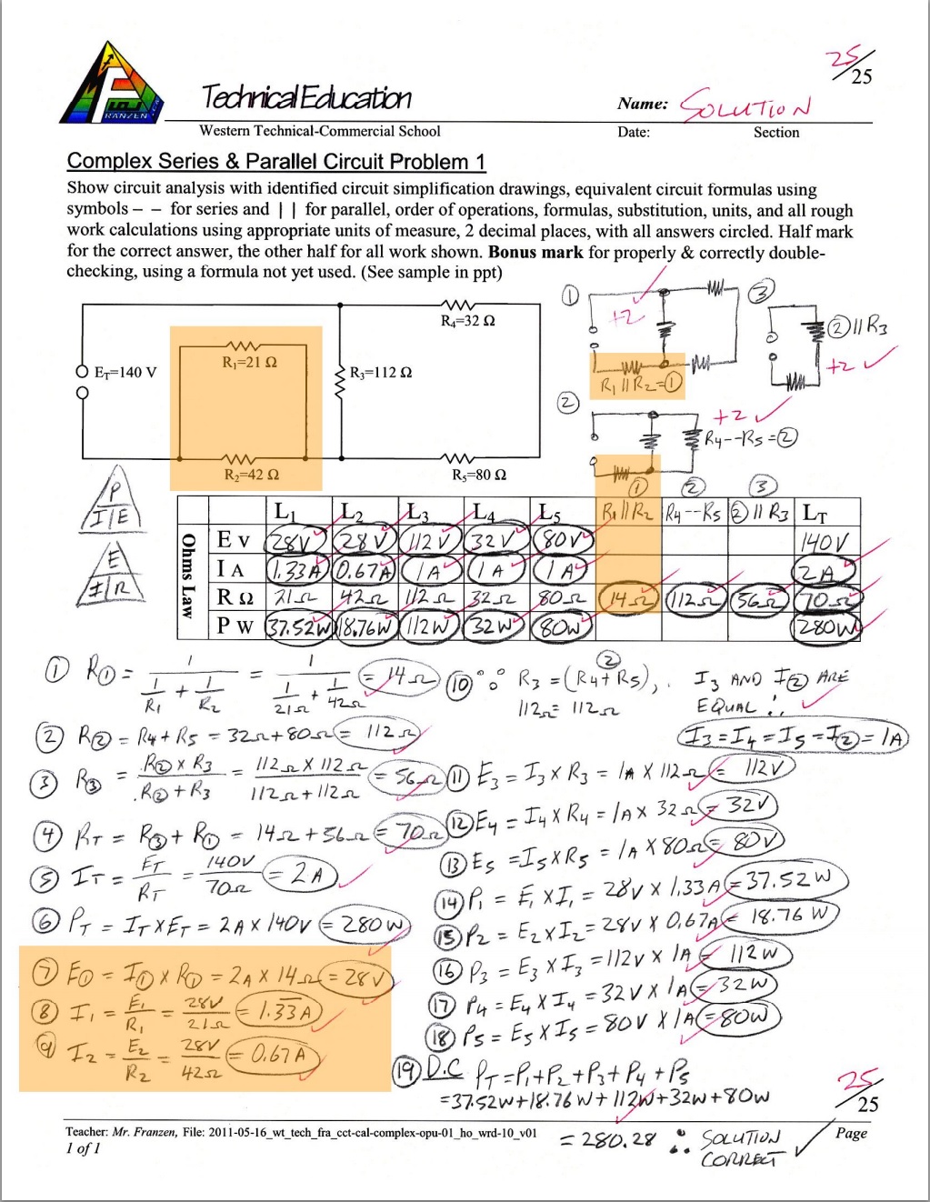
Complex Cct Calculations
- Referring to the above Circuit Theory Power Point presentation, you can follow the complex circuit breakdown analysis. For the sample question to the left, note how the circuit drawing is simplified each step from a to e. These steps are explained in detail here if you wish to review it one more time.
- Your first assignment
 Complex Series/Parallel Analysis Variable will be to analyze and simplify the circuit without calculations. Simplify and redraw the circuit however many times you need to get a final complex statement using letter variables. Although not shown in sample, use different brackets to show variable order.
 - Putting it all together, take a look at the sample complex Series/parallel circuit solved. Your next assignment Complex Series/Parallel Analysis and Calculations you will do the same and additionally calculate all the unknowns using ohms law, power, series, and parallel formulas, calculations, circuit diagram simplification and circuit analysis. Use the sample to the left as an example of process and expectations for your circuit challenge problem.
Evaluation:
Each circuit assignment problem must show all work to get full marks and once taken up in class, 50% of the lost marks can be reclaimed that day, by showing the corrections completed on a separate area with a different coloured pen with a title above stating "Corrections @ 50%".

| Evaluation Breakdown Component Descriptions For Presentation | Marks |
|---|---|
| Always double check that you have completed all components for full marks. | |
| Series Intro Sample - copied neatly in pencil showing all formulas and calculations | 10 |
| Series Practice - order of operation, all formulas, quantities, and calculations | 12 |
| Parallel Intro - order of operation, all formulas, quantities, and calculations | 12 |
| Parallel Practice - order of operation, all formulas, quantities, and calculations | 12 |
| Series & Parallel Cct 0 - order of operation, all formulas, quantities, units, and calculations | 24 |
| Series & Parallel Cct 1 - order of operation, all formulas, quantities, units, and calculations | 24 |
| Complex Series/Parallel Analysis Variable -cct diagram simplification and final variable | 10 |
| Complex Series/Parallel Analysis and Cal.- diagram simplification and all unknowns | 25 |
| Series & Parallel Test - order of operation, all formulas, units, and calculations | 24 |
Unit 3, Act. 3: Logic Gates
Situation:
Getting an a better understanding how computers use digital data to function supports logic gates and their operation.
Problem/Challenge:
Familiarize with digital logic gates symbols, Boolean functions and common digital logic ccts will be reviewed. Students will also look at common electrical/mechanical circuit designs and apply those designs to digital logic circuits.
Investigation/Ideas:

Digital Logic
Digital Logic is important aspect of how computers work. They all work on the same principle which is manipulating on/off signals to implement logic functions. Over the years there have been many ways to create those on/off signals such as mechanical devices, relays, vacuum tubes and now transistors and ![]() IC chips, 5.26 which have revolutionized digital logic as it is used today. Looking closer at digital logic gates, Boolean, and their operations supports the understanding on how computers work.
IC chips, 5.26 which have revolutionized digital logic as it is used today. Looking closer at digital logic gates, Boolean, and their operations supports the understanding on how computers work.
Logic Gates

Logic gates are the fundamental basic components in digital electronics. They are used to create digital circuits and more advanced various integrated ready-to-use common circuits/chips such as multiplexers, registers, arithmetic logic units (ALUs) and computer memory all the way up to advanced complex circuit/chips such as microprocessors/microcontrollers, which in turn are used in calculators and computers. Boolean functions can be practically implemented using electronic gates. Digital electronic gates are made up of inputs, internal transistor ccts, power supply/ground return, and an output. The inputs of a gate are driven by two nominal voltages 0V and 5V (3.3V on newer gates) representing logic 0 and logic 1 respectively along with the output having the same output voltages and logic. There is always a relatively slight time delay between an input being applied to the output responding, which is called the propagation delay, or just plainly the gate delay.


There 7 standard logic gates; AND, OR, NOT, NAND, NOR, XOR, and the XNOR. More specially AND, OR, and NOT are the three basic gates that can be used to make any gate. NAND and NOR are considered universal gates (and because they are easier to design, therefore less expensive, and can be implemented into other function gates), and can and XOR and XNOR are derived gates. Logic gates can be made with multi-inputs. Each have there own characteristics in operation and compared by their gate name, symbol, notation, and truth tables. Each gate is made up generally with transistors to operate/behave with their standard rules. Older logic gates made with TTL logic will work at ~ 5v while newer CMOS logic working at ~ 3 v. An example of what you may find is shown in the Whats inside? image thumbnail link using a NAND gate, along with a simplification to the basic symbol that is commonly used.
Familiarizing yourself with each of the common gates along with some simple circuits, you can build some practical circuit projects. A great way to learn how digital logic circuits work is to look at basic mechanical circuits which are made up of control (switches, push buttons, relay contacts, etc) and loads (lights, motors, coils, etc). Compare them to digital logic which will have inputs (contacts for feeding high/low), functions (logic gates), and outputs (lights, displays, data).

Boolean Logic

Boolean by its self is commonly used when doing searches on the Web and is refereed to a system of logical thought developed by a English mathematician and computer pioneer, ![]() George Boole, 1.43 (1815-64). As you already know, doing a search using Boolean, a "and" operator between two words or other values means one is searching for information containing both of the words or values, not just one of them where a "or" operator between two words or other values would mean you would be searching for information containing either of the words. The Boolean system remained as theory and academics until the early 1900s, when electrical engineers noticed its power for "switching circuits", leading to telephone networks and digital computers
George Boole, 1.43 (1815-64). As you already know, doing a search using Boolean, a "and" operator between two words or other values means one is searching for information containing both of the words or values, not just one of them where a "or" operator between two words or other values would mean you would be searching for information containing either of the words. The Boolean system remained as theory and academics until the early 1900s, when electrical engineers noticed its power for "switching circuits", leading to telephone networks and digital computers
Boolean applied to digital logic can be used in circuit states that are either charged (1 or true) or not charged (0 or false). The computer can use this logic state such as a AND gate or an OR gate to obtain a result that can be used for further processing. Some real examples could include conditional statements in programming, search engines, algorithms, and formulas. Using combinations of logic gates as learned above, complex operations can be performed and in theory, there is no limit to the number of gates that can be joined in a single device, but hardware capacity will limit the number of gates that can actually be realistically used. It is then useful to write in a simple mathematical formats, equation representing a logical operation.

Table showing Boolean algebra laws
- A AND B should be written as AB (or sometimes A • B)
- A OR B should be written as A + B
- A XOR B should be written as A ⊕ B
- NOT A should be written as A' or A
- A NAND B is written as (AB)' , (A • B)' , or (AB)
- A NOR B is written as (A + B)' or (A + B)
Boolean Algebra and Operations
Using Boolean algebra, logic gate circuits can be simplified using the basic Boolean algebra laws such as annulment, identity, indempotence, complement, commutative, double negative (compliment), distributive, absorption, and associative. De Morgan also developed a pair of rules/theorem that are the most powerful identities in Boolean algebra.
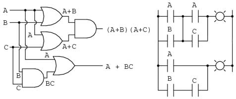
Simplification of complex logic circuits using Boolean algebra can allow you to reduce the numbers of logic gates without changing the function of the circuit and therefor reducing the cost and gate delay. By using the digital logic gate circuit algebraic notation of the whole circuit and the laws, you can then simplify the circuit to use less gates for the same resulting output. This takes some memorization of the laws and practice with simplification operations to be familiar and fluent in this process. Therefor you can mathematically simplify a digital logic circuit using the equivalent algebraic notations and some math simplification.

- Logic gate
- Logic gates Intro
- Intro to logic gates
- AAC - Symbols
- AAC- Circuit Equivalents
- AAC - Logic Gates
- Logic gates explained
- Digital logic
- Sensors and logic gates, 49s
- Binary logic, 44s
- Intro to Boolean algebra
- Boolean algebra and logic gates
- Boolean logic and logic gates, 10.06
- Logic Simplification, 9.46
- Logic Simplification, 34.36
- Boolean algebra simplification, 9.39
- Boolean algebra review
- AAC intro to Boolean algebra
- AAC Cct simplification examples
Resource Support Links
Create/Construct:
Students will familiarize themselves with logic gates, circuit design steps, and Boolean through the following assignments:
- Fill out the 6 main logic gates handout with their notation, truth table, and mechanical circuit equivalent (12 marks)
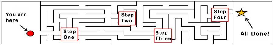
- Divide the back of the page into three equal spaces for the following: Title: Circuit Design Steps, then neatly name and describe in 5 major steps to design and create a working circuit design using the SPICE model and circuit design goals (5 marks)
- Title: Stop/Start Motor Control Electrical Ladder Schematic Cct and neatly sketch out (copy) the Stop/Start motor control schematic (not power cct) with the proper symbols carefully drawn out and labeled, while noting the latching safety cct design (5 marks)
- Title: Stop/Start Motor Control Digital Logic Cct and neatly design a working logic control circuit that operates with the same control function as the electrical cct above. Control/input on the left, functions in the centre, and output on the right using appropriate labeled symbols and wire connections to show a working stop/start cct with the latching safety design implemented (10 marks)
- Complete Digital Logic Gates, Boolean, and Operations Review questions
- Next activity you will be designing and creating virtual digital logic circuits
Continue to finish off computer project tasks, and start to work on your Raspberry Pi beginner projects you researched earlier.
Evaluation:
The following is a breakdown of marks related to digital logic, circuit design steps, Boolean, and continued weekly practical work assigned.

| Evaluation Breakdown Component Descriptions | Marks |
|---|---|
| Always double check that you have completed all components for full marks. | |
| Logic Gate Table - fill in symbols, notations, truth table, and equivalent cct | 12 |
| Circuit Design - List the 5 steps with descriptions | 10 |
| DL, Boolean & Operations Rev - Complete all questions | 20 |
| Task Tracking - Weekly computer task log on related practical work | ~30 |
Unit 3, Act. 4: Design, Build, and Analyze Digital Logic Circuits
Situation:
By directly designing, building, and analyzing your own digital logic circuits, students will be able to learn valuable practical hands-on experience.

Problem/Challenge:
Look at some common electromechanical circuits, compare and build similar operation using digital logic gates. Review and build common digital circuits used in computers that count, calculate, store memory, and work as a whole.
Investigation/Ideas:

Digital Circuits
So where does all this lead to? Binary, binary conversion, logic gates, and Boolean lead us to creating efficiency computer digital circuits that can follow instructions from programming code. Some common programming code types you may have come across are Turing, Basic, Arduino, Python, Java, C, etc that are used to instruct the computer to complete tasks that are part of an application designed to help you with a task, whether it is to calculate/solve for a solution, view images or videos, move data, and/or communicate.


Digital Logic Circuit Design and Building
Looking at a familiar common electromechanical circuits, components (symbols), and their operation helps you understand basic circuit function. Comparing and transferring similar operation, using digital logic gates, will help you understand each of their characteristics, better your understanding, and allow you to learn and create equivalent digital logic circuits. Through this process, you will better understand building equivalent digital logic circuits, working with truth tables, and circuit simplification.
The basic push button ladder schematic ![]() control circuit to the right has two normally open push buttons that need to be both pushed in order to energize CR1 (control relay 1) which in turn will change the state of the related CR1 contact on the next rung, turning the output M (motor) on.
control circuit to the right has two normally open push buttons that need to be both pushed in order to energize CR1 (control relay 1) which in turn will change the state of the related CR1 contact on the next rung, turning the output M (motor) on.
Looking at our logic gate characteristics, their truth tables we can see that two buttons in series represents an AND function. So to build the equivalent circuit to the electromechanical we add two momentary open push buttons as inputs (I1 & I2), a AND function going to an output Q1.
This was a very simple circuit. As circuits get more complex, knowing how your logic gates work, their truth tables, and key operation characteristics, you can design and build equivalent digital logic circuits. Circuit design is not just about taking the appropriate SPICE steps but also being able to break a circuit down to its logical components, then translating it to digital logic a piece at a time.
Logo!Soft is a free virtual digital logic design program that you can use to test different digital logic circuits without having to purchase hardware, waste time manually building, to only find that it may not work. This program allows you to quickly design and test real circuits virtually, allowing you to more time to learn about digital logic gates. This program has extensive support and help files and comes with sample files you can review.
Specific things to review in this program to allow you work with the program are as follows:
Digital Logic Adder
Half Adder

Add Two Half Adders
Shown with block symbols
Full Adder
- User Interface
- Standard Tool bar Tools
- Simulation Tool bar Tools
- Standard inputs - I, such as push buttons and switches
- Basic digital logic gate functions
- Standard outputs - Q, such as relay coils
LogoSoft Virtual Simulation Software
You will need to familiarize yourself with the LOGO! Soft Comfort software program through the use of the program it's self and the help section. Below are some links to download this free application. Use the first link for a Win64bit small exe install file. If you are on another system, use the third link which has all system installs:
- LogoSoft Comfort Demo 8 - Win64 setup.exe
- LOGO! Soft Comfort software (Links on site page currently not working Jan 2021)
- logo_soft_comfort_v8_demo (1.52 GB zipped file)
Computer Digital Circuits
Digital logic circuits can be broken down into two subcategories: combinational and sequential. Combinational logic are build on the five basic logic gates plus the inverter and have relatively no gate delay while sequential circuits have propagation through stages of the circuit based on the edges of clock signal that they use. Because combinational circuitry can be "glitchy" based on a variety of delays (such as the manufacturing process of the parts involved, the temperature of the silicon, and the complexity of the circuit), sequential circuitry only samples results at specific times, that is synchronized with system. Latches and common flip flops such as the D type, T type, and JK type all have specific characteristics on their operation and operate based on this clock in the real world, so they don't glitch out.
Digital integrated circuits (IC) come in many variations. Take a look at the list of 7400 series of IC chips, and you will find many to choose from. IC chips can be found in microcomputers, memory, and standard logic to implement particular functions and custom logic for needs of a particular user. There are about 600 types of standard logic ICs from basic chips to complex functional arithmetic and logic units with two different types: TTL and CMOS. TTL (transistor-transistor logic) mainly built with bipolar transistors that run on 5 volt while CMOS (complementary metal oxide semiconductor) are built from pairs of p-type and n-type metal oxide semiconductor field-effect transistors (MOSFETs) with voltages having a wide range (commonly use a lower 3.3 volts).
Digital Adders
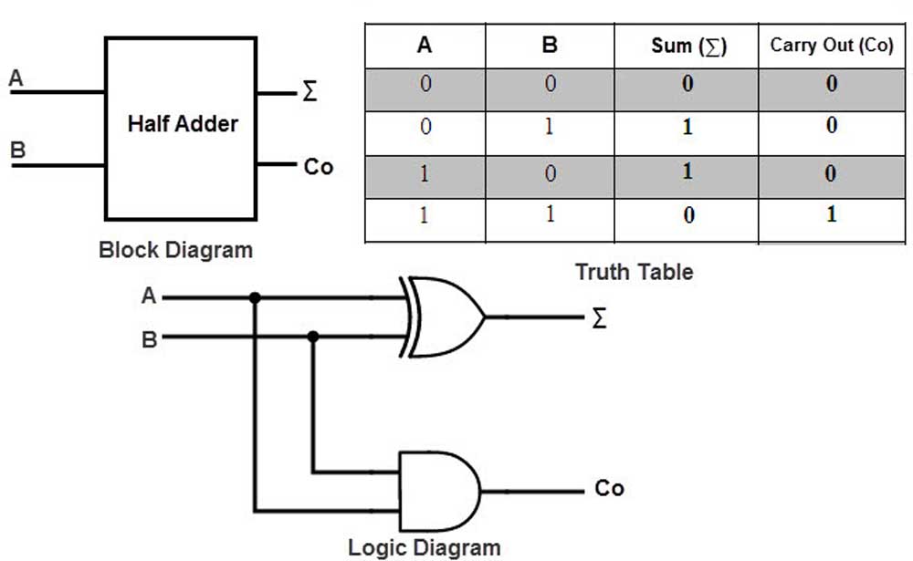
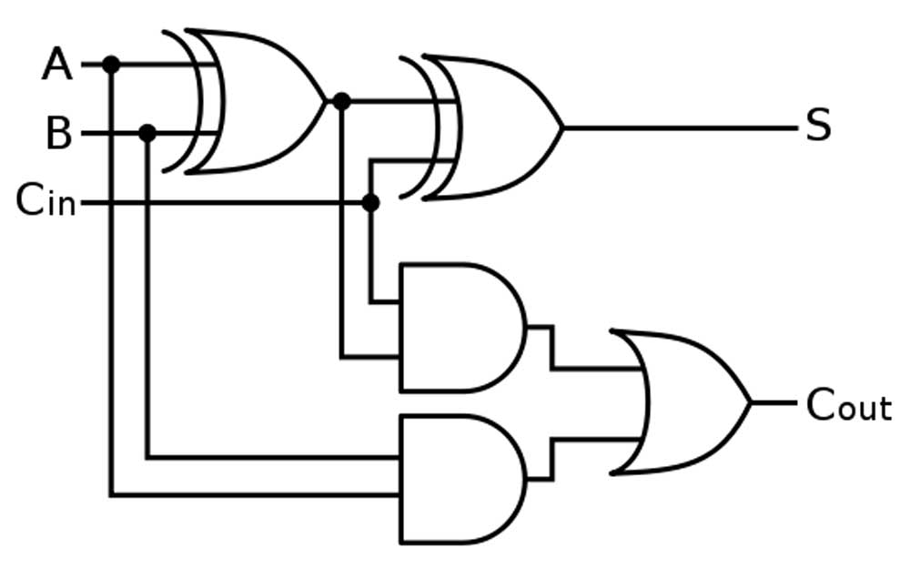
As we previously took the time to understand how binary is added, we can also apply this to digital logic circuits to do this. Using two inputs connected parallel with a XOR gate and a AND gate, we can see by the generated truth table that we get correct addition of both bits with the sum bit and the AND which creates the carry operation. This is called a half adder, as it adds one bit with ability to carry. A and B are commonly the inputs, Cout is the carry out, and the ∑ is the summation output, also expressed as an S.
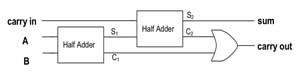
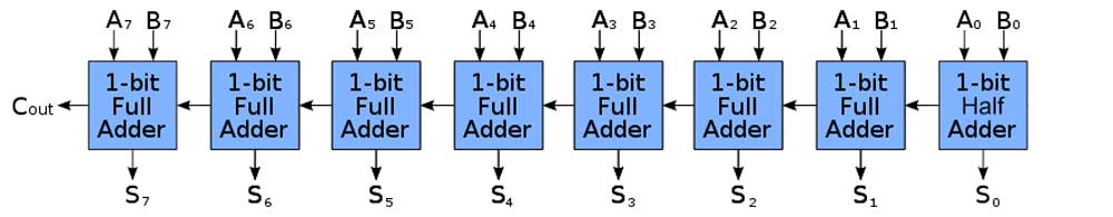
By combining two half adders and also an OR to take the carries from both of the AND's from each half adder, the output carry will continue to output properly resulting in a full adder circuit. A full digital adder performs addition two one bit numbers and an input carry. To perform more than one bit addition, a parallel adder must be used for adding all required bits simultaneously. In a parallel adder circuit there is no carry at the least significant position, therefore you can use either a half adder or make the carry input of full adder to zero

Resource Support Links
- Ladder Logic in Detail
- How computers add numbers, 14.26
- How computers calculate, 11.09
- Binary Adder and Subtractor
- What is the full adder?
- Computer memory, 12.16
- The central processing unit (CPU), 11.37
- Digital Systems
- Different Types of Digital Logic Circuits with Working Conditions
Create/Construct:

A) Digital Logic Circuits
Complete the review questions on Digital Logic Circuits. Use the information above, lesson points, and resource links to complete the answers.
B) Logo!soft - Four Bit Adder Circuit Build

- Using LOGO!Soft open up a new file and name it appropriately with your course code_project_last initial- first name
- Create a full adder circuit, check it's operation to ensure it is working
- Review half and full adder digital logic circuits, then create an 4 bit full adder circuit
- Ensure you have a title, circuit description, name at the top, label your adder circuit functions, inputs/outputs with standard lettering and numbering
- Once you have finished the circuit test to ensure it is working correctly, wiring is organized, and have your partner double check it and hand-in both the .lsc and an exported .jpg file (remember proper file naming convention)
![]() : Re use template supplied as sample file
: Re use template supplied as sample file
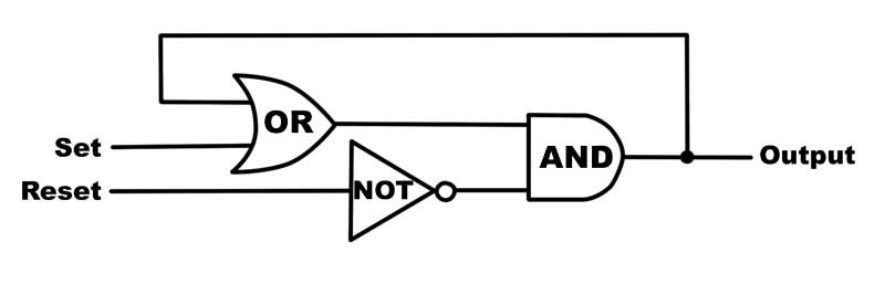

Latch Control

If you have time, you can try to create an eight bit adder circuit.
C) Logo!soft - Stop Start Motor Control Circuit Build
- Create an equivalent logic gate circuit that does the same as the electromechanical stop/start motor control circuit
- Insert title, circuit description, name, and sub titles for Inputs, Functions, and Outputs using the text tool using the full screen with reasonable zoom, configuring each as needed including switching options, comments, labels, etc.
- Connect up wiring with mimimal wire crossings, organized, and ensure objects are aligned
- Simulate and test to see if circuit is working the same as the electromechanical circuit
- Save, and have your partner check your work and drop-off both the .lsc and an exported .jpg file

D) Logo!soft - Forward/Reverse timed Motor Control Circuit Build
The Forward/Reverse Motor control circuit (power cct) is a common control circuit in motor control using two latching safety ccts along with interlock, so that the motor can only run Forward or Reverse direction at one time. At shelf state, if the forward or reverse momentary push button is pushed, that direction of the motor will start immediately. If running in a forward or reverse direction, the opposite direction will not be able to start until the stop button is pushed and 10 seconds have passed by (timer). View sample diagram for electrical/mechanical cct operation to convert and design a digital Logic version using logic gates to produce the same circuit operation with a timer delay.
- Using the LogoSoft digital logic sample circuit .LSC file as a template, create a new file and name it appropriately with your Last initial, first name, - project name
- Insert title, name, date, section#, given cct operation, and Subtitles for Inputs, Functions, and Outputs using the text tool
- Insert and align your Inputs (on left), Outputs (on right), and Functions (in centre) using the full screen, configuring each as needed including switching options, labels, comments, etc.
- Connect wiring minimizing wire crossing, ensuring it is neat, components are organized, and aligned
- Simulate and test to see if circuit is working the way it is required
- Submit the LSC file and a PDF file with the proper file naming convention
- Your Digital Logic cct to fill the PDF page (zoom, if necessary, prior to exporting) should fill PDF page fully
- With LOGO!soft using the following circuit diagram given , create the digital logic equivalent using any of the common logic gates following the same process as last circuit design
- Remember that the latch circuit function is very similar to the last project and can be duplicated here for both the forward and reverse circuit
- One additional step will require a 4 second delay between switching directions.
- Once you have a finished and circuit is working correctly, wiring organized, and labeled have your partner double check it and hand-in both the .LSC and an exported .PDF file
Note: Best designs will have the least number of logic gates, so keep this in mind and always see if there is a better way to minimize the number of gates you use.
Breakdown (Out of 35):
- Header - title, name, date, section #, cct description, sub-topic headers for inputs/functions/outputs /5
- Circuit Organized, aligned, configured, labeled, filling PDF page, minimized wire crossings, with neat wiring /10
- Forward and reverse latched cct function working independently /10
- Forward and reverse interlocked (prevent other direction starting if already running) /5
- Timer cct delay after stop has been pressed to change direction /5
Evaluation:
The following is a breakdown of marks related to the three digital logic gate circuit problems and continued weekly practical Raspberry Pi work.
| Evaluation Breakdown Component Descriptions | Marks |
|---|---|
| Always double check that you have completed all components for full marks. | |
| Digital Logic Circuits - Complete all questions | 17 |
| Four Bit Adder - Working 4 bit adder circuit, organized, labeled, lsc/jpg | 15 |
| Stop/Start Mtr Cct - Equivalent with description, labels, neat, lsc/jpg | 15 |
| Forward/Reverse Cct- Equivalent with timer delay, description, etc. | 35 |