Unit 3: Introduction to Creo Elements Pro Engineer
This unit will introduce you to Creo Elements Pro Engineer and allow you to print your projects with our BFB 3000 3D printer.
Unit Content Activity Quick Links, Click to Jump to Specific Activity!
- Unit 3, Act. 1: Creating a Simple Key Fob
- Unit 3, Act. 2: Custom Key Ring Accessory
- Unit 3, Act. 3: Flat Ring Design and The Design Process
- Related TDJ2O1 Course for Next Year
 Unit 3, Act. 1: Creating a Key Fob

Situation:
Being new to Creo Elements Pro, this project will help familiarize you with the basic tools of creating a 3D model part. 3D models can be then converted to print the object in 3D using a plastic compound delivered by filament rolls.
Problem/Challenge:
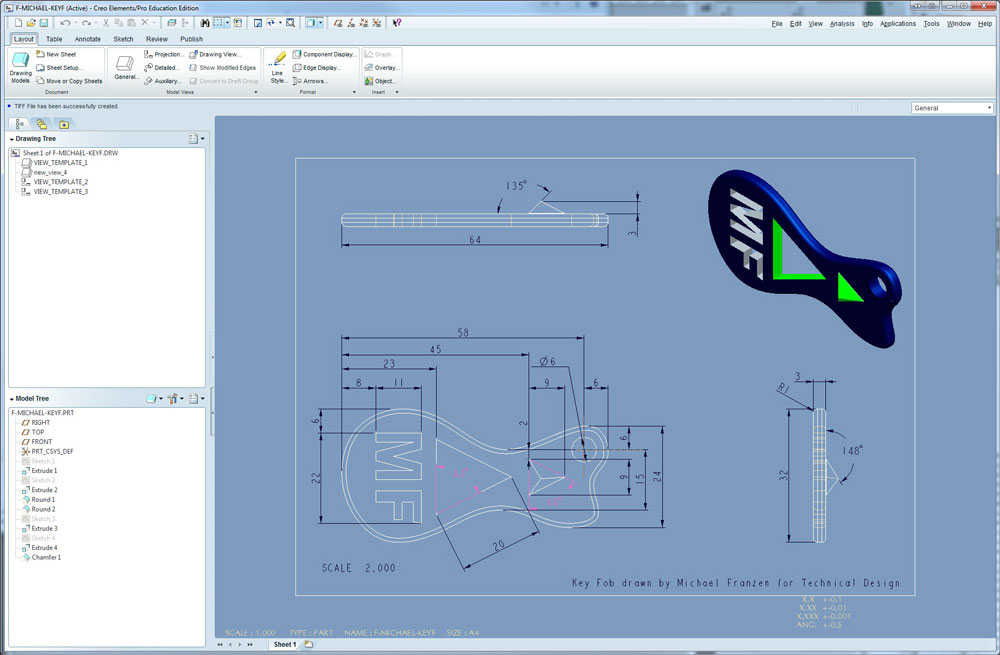
Your challenge is to review and learn about what Creo Elements Pro Engineer is, it's history, and the basic tools of the program to create a key fob through the use of a guided PDF tutorial. You will create a similar design and add your initials. Once finished the tutorial, you will create a print file using a conversion program called Axion to print your project in 3D. Meanwhile you will also create a new drawing file showing third angle orthographic projections with overall and detail dimensions and a suitable isometric as learned in class with the step block.
Investigation/Ideas:
This 3D model is going to be created using Creo Elements/Pro. It is a parametric driven, integrated 3D CAD/CAM/CAE solution, used by discrete manufacturers for mechanical engineering, design and manufacturing. With all of the previous experience with sketching, 2D drawing, and 3D modeling, this should be easy to pick up the basics, as you are already familiar with the previous programs used. The tutorial in the next section will guide you step by step to the end of the creation of your customized key fob. There are several resources on the web that can be helpful when familiarizing yourself with a program of this magnitude.
- Wikipedia on Creo Elements
- Main Browser Page
- Creo Elements/Pro 5.0
- 3D BFB 3000 3D printer Site
- 3D BFB 30000 Manual

- Orthographic Drawing in Creo

Create/Construct:
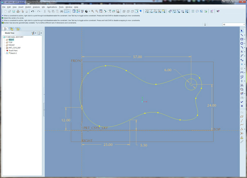
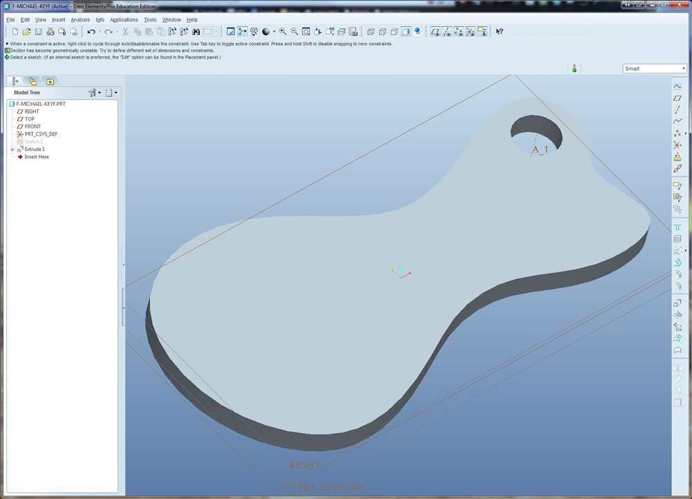
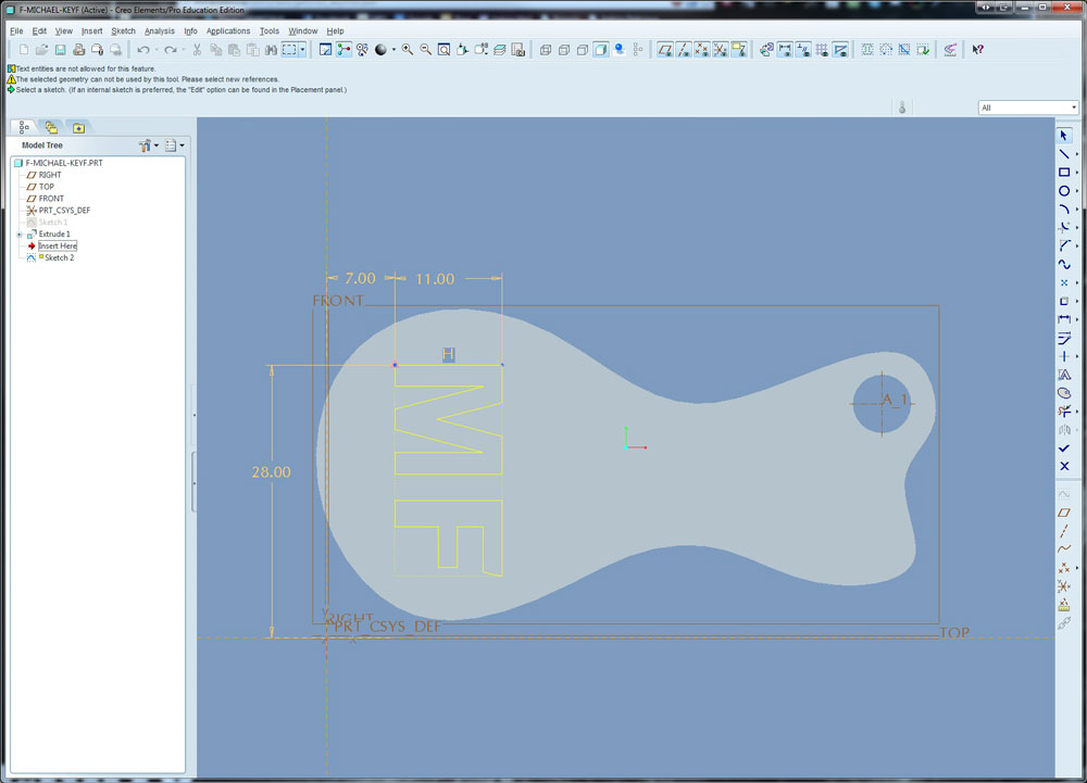
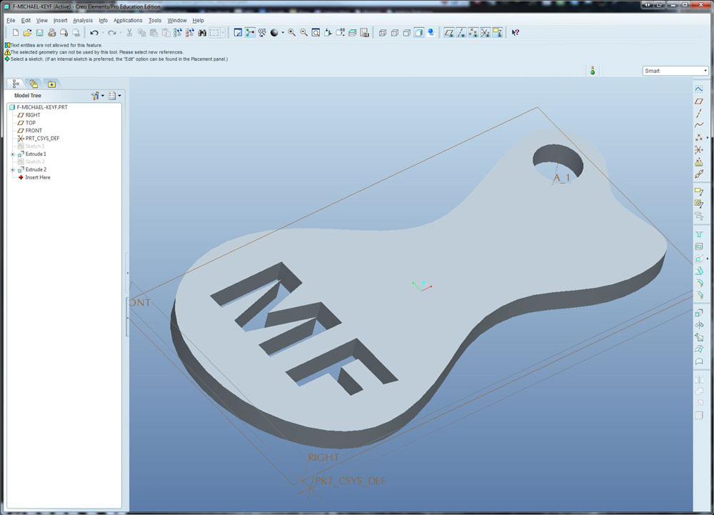
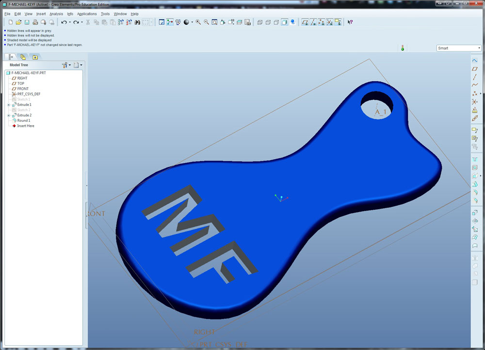
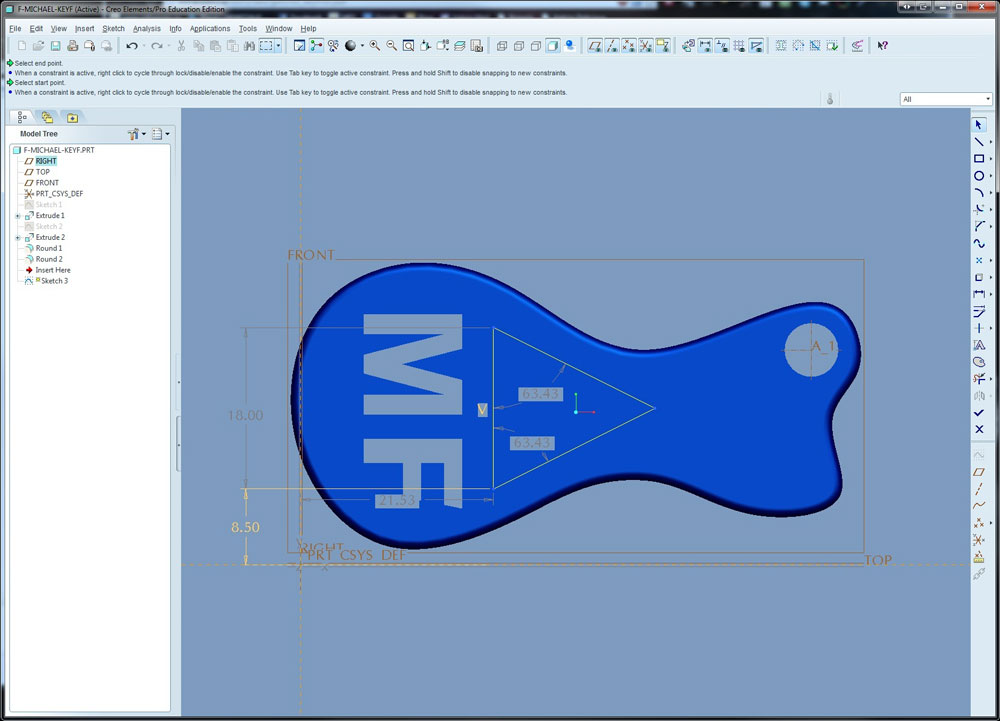
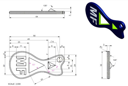
Follow this tutorial to create a key fob, with the exception, using your name initials. When you start drawing, remember the three rules on picking the front view and then ensure that you draw it with the length across the page. When you create your first sketch, ensure your dimensions are organized by moving them to appropriate locations outside the image. Remove the extra material in the key fob as suggested at the end of the tutorial. It is recommended to use the Grotesque MT Bold font for your letters as they are wide and easy to read.
Model Sample 1
Model Sample 2
Model Sample 3
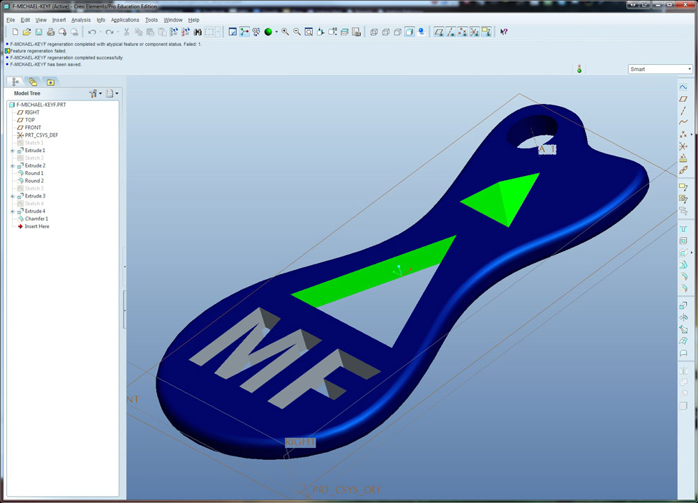
Model Sample 4
Model Sample 5
Model Sample 6
Model Sample 7
Model Sample 8
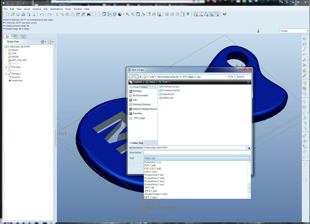
 The key ring hole must have a minimum of 3-4 mm of material around for strength. Once you have finished your 3D model, you need to save it in its proprietary form .PRT, image form .JPG, portable file format .PDF u3d in landscape format, and lastly a conversion file .STL (see below at the end of activity for more info on file formats). When saving it in .JPG format turn off all the different auxiliary viewing such as planes, axis, origin, etc by clicking on the respective icons at the top of the screen.
3D Printing
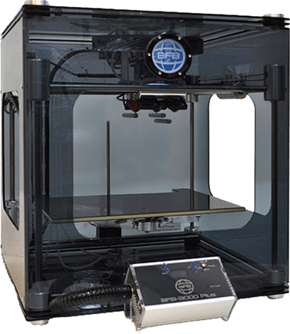
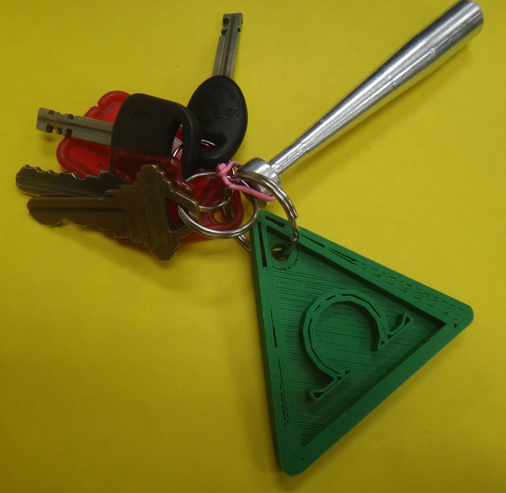
With the 3D BFB 3000 3D printer, you will be able to print your design in 3D. A little history and general information can be found here. Note this unit has a lot of settings and maintenance issues which you can find in the manual ![]() , so make sure you check with instructor before using every time! It is also important to understand a simple small print such as the example key fob below will take about a half hour, so you may need to come between classes, before lunch, or after school to ensure you do get your project printed.
, so make sure you check with instructor before using every time! It is also important to understand a simple small print such as the example key fob below will take about a half hour, so you may need to come between classes, before lunch, or after school to ensure you do get your project printed.
You will need save a copy as, of your final (instructor checked design) as an STL file in Creo. Using conversion software from Axion you will be able to build a BFB print file from your exported standard STL file. This will take several minutes depending on the complexity of your design. This file will have to be saved on a SD flash card and inserted into the BFB 3000's control box before your print can be initiated.
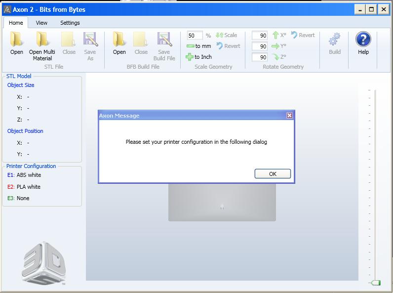
Ensure you ask your teacher which printer and configuration settings will be used, as it will depend on the type and colour of plastic being used in each of the three extruder heads of the 3D Printer.
You can watch the video and/or see the steps below for proper set-up and operation of Axon:
Step 1
Start Axon2
Step 2
Configuration Window
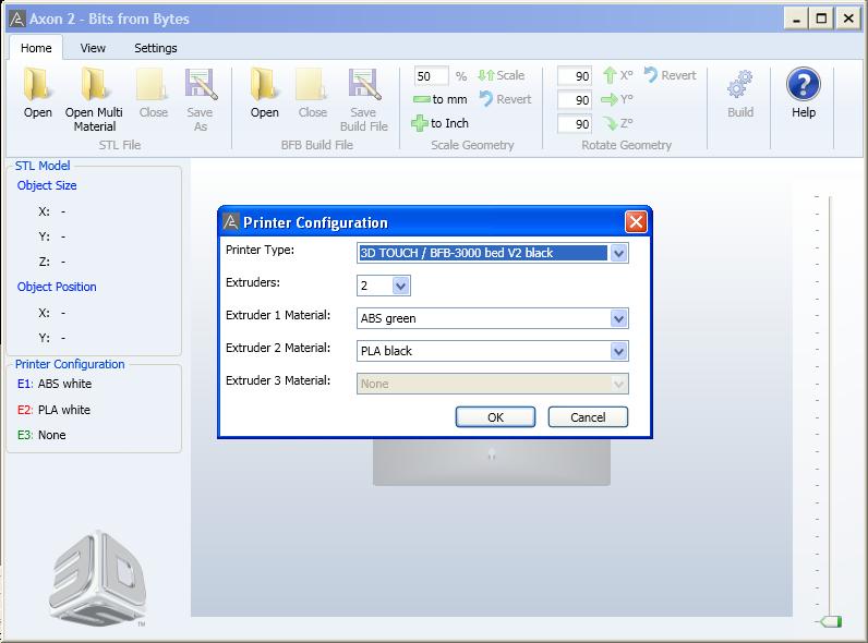
Step 3
Set-up Printer
Step 4
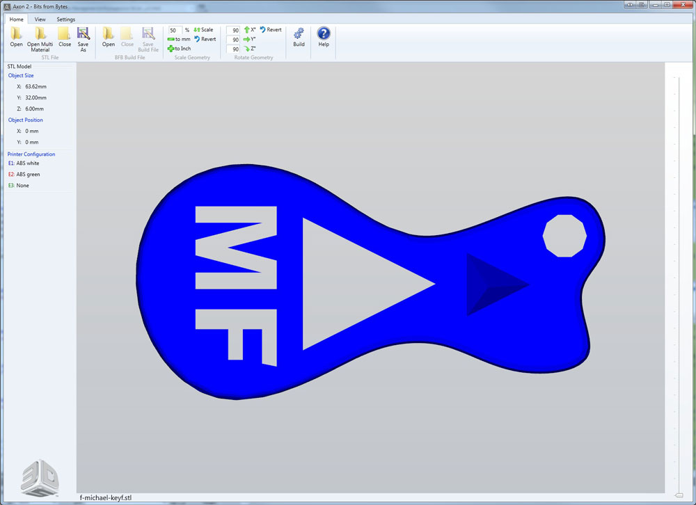
Open STL File
Step 5
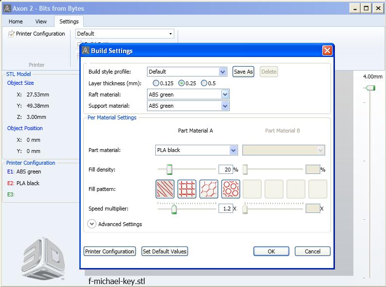
Build Settings
Step 6
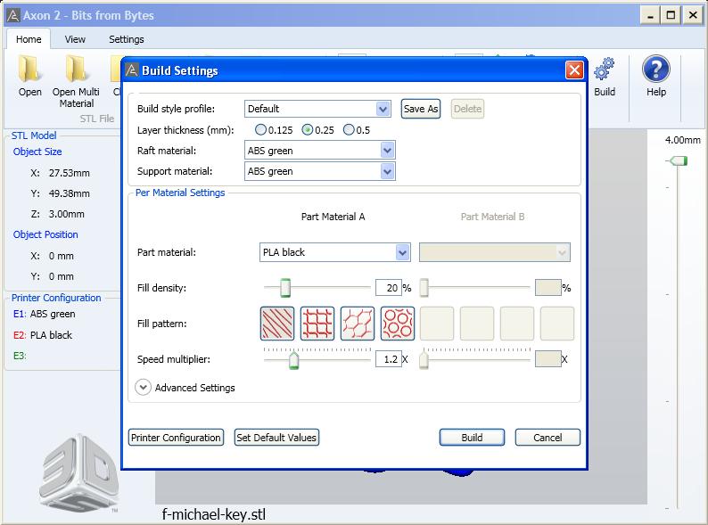
Build Window
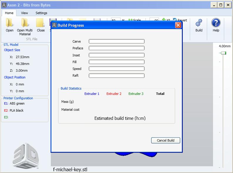
Step 7
Build Start
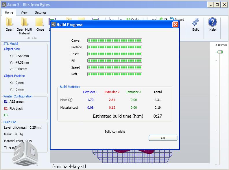
Step 8
Build Finished
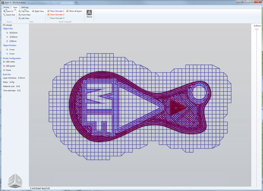
Step 9
Build Preview
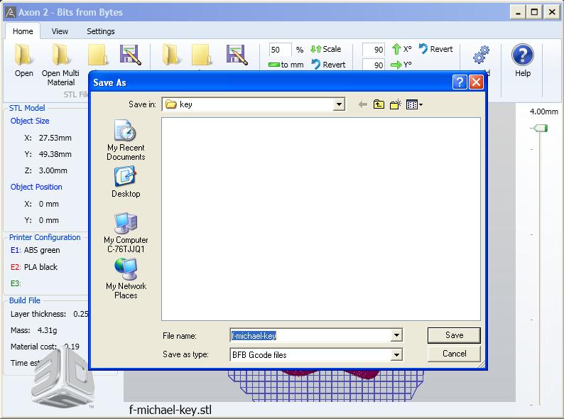
Step 10
Save BFB File
Interesting FAQ's About This Printer:
- Can be used with any CAD program that has the ability to export .STL files
- Supports two thermoplastic materials: PLA and ABS
- PLA is the easiest material to work with and is considered a biodegradable thermoplastic that has been made from renewable resources such as corn starch and sugar cane. It is a preferred choice for support material, but will go brittle when exposed to sun and air in a short time, and is for this reason we will not normally be using it.
- ABS is the second easiest material to work with and is an engineering polymer commonly used to produce car bumpers due to its toughness and strength. It does however have a tendency to warp on larger geometries but is very stable in not going brittle like PLA
- Support material is used to make scaffolding in low resolution to support the geometry of a model which otherwise would be printed in mid-air, can be removed by simply breaking it away off of your printed part and then sanding or filing to finish off. Alternatively, you can remove PLA support material by carefully hydrolysing in sodium hydroxide to melt it away, or by soaking in 80°C water for 48 hours which makes it extremely brittle and easier to remove.
- Finish surface quality depends on the geometry and layer thickness you are printing with. For example the 0.125mm layer thickness will result in a smoother surface compared with the 0.25mm layer thickness, however it will take longer to print.
Once you have your BFB printer build file, you can load it on to the SD card using the plug-in-adaptor, then plug the SD card into the 3D BFB printer control panel slot. If everything is ready (check with your teacher) then you may run your file / print your key ring accessory. It is important to watch the beginning to ensure print does start correctly, by printing the raft then your design.
Orthographic Projection Drawing & Dimensioning Steps:
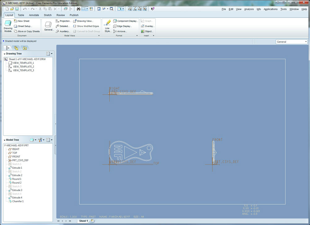
- Starting a New Drawing: Open your completed key fob model, then create a new file, and select drawing (DWG) as your new file type, default template, A4 size, same file name
- Scale & Display Options: In created drawing, on layout tab, left mouse button, double click front view and adjust scale and view display-settings if needed
- Adjust View Locations: With mouse on front view, right click and hold for a second to get sub-menu, and unlock view locations, and move ortho views to suit
- To show Grid: Sketch tab, select grid - in grid menu-grid pram -X&Y Spacing to 10 then select done, select show grid
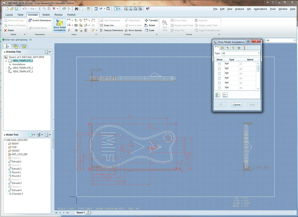
- Dimensions: On Annotation tab, with a view (front first) selected, click on Show Model Annotations, check all you want, then manually locate using grid
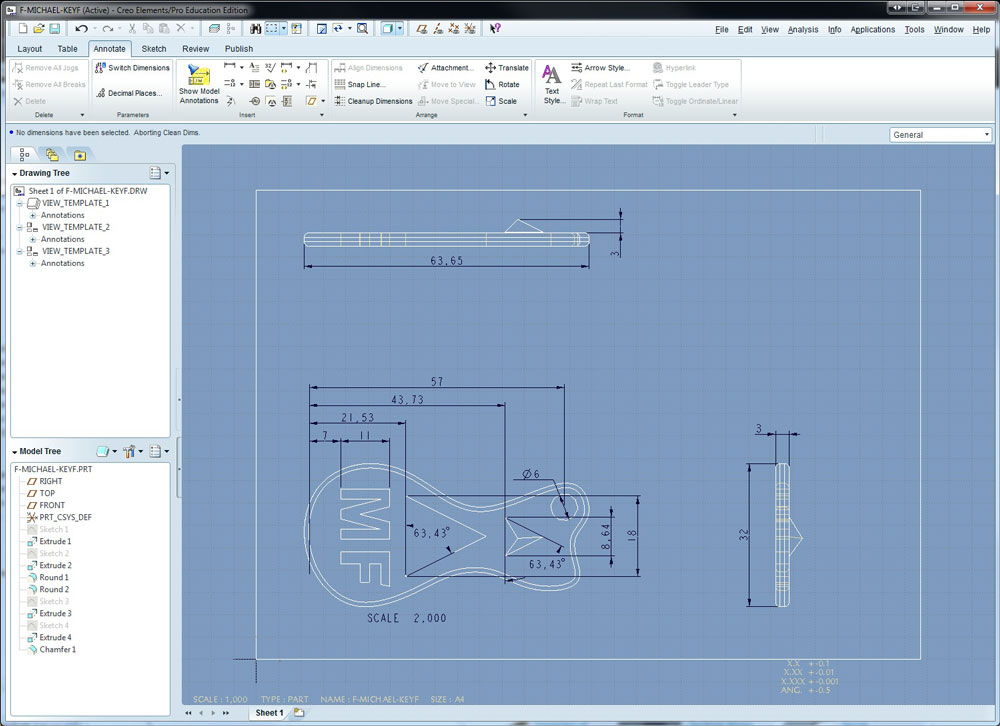
- Dimension Clean-up: Select view to work on, then select Cleanup Dimensions, fill in 10 and 8 for spacing, and apply
- Dimension Hole Centre lines: On Annotation tab, click on Show Model Annotations again, this time in the sub menu select the last tab icon for hole centre lines
- Dimension Hole Location: Select Dimension New References, in menu select On Entity, then select centre line, then outside of object, middle button to place
- Insert Isometric View: On layout tab, click general view, left click where you want it, then change default orientation to Isometric, adjust scale
- ID Note: Annotation tab select note icon and type in Key Fob by (your name) for Technical Design and locate bottom right
TIP: Use the refit icon (located top with view icons group) when you want to zoom out to see the full drawing on your screen. For manual dimensions you will need to experiment with the pop-up menu to manually add dimensions for specific detailed features.
DWG Sample 1
DWG Sample 2
DWG Sample 3
DWG Sample 4
File Formats & Handing in Work
Once done all work, carefully delete all old versions of the model and drawings by going into File menu, selecting Delete, then select Old Versions, then you will be able to submit submit just your current final files in the hand-in-folder as discussed in previously in class. Remember if you want to change the file name, use the "Save a Copy" to change the name and/or export your file to a different type by selecting in "Type" such as a JPG, a PDFu3D, or a STL file. Ensure the file extension is correct and present. Here are some examples of file name you should be using:
- PRT - Creo model part:: d-joe_keyfob.prt
- PDF u3d - Portable File Document (u3d is a special format for viewing a dynamic part model): d-joe_keyfob.pdf
- JPG - Joint Photographic Experts Group: d-joe_keyfob.jpg
- STL - STereoLithography: d-j-keyf.stl (note only the first 8 characters of file name will show, more than 8, will only show 6)
- DRW - Creo drawing: d-joe_keyfob.prt
- PDF - standard Portable File Document: d-joe_keyfob-d.pdf (note -d, as to not overwrite the u3d)
Evaluation:
Ensure you have followed the tutorial correctly creating a similar key fob using the same tools in Creo. Make sure you name your files as learned in the first unit and hand into the correct hand-in folder.
| Evaluation Breakdown Component Descriptions | Marks |
|---|---|
| Always double check that you have completed all components for full marks. | |
| Tutorial: completed following all steps in - PRT, PDFu3e, and a JPG files | 20 |
| 3D Print: BFB file converted, key fob printed successfully and cleaned up | 10 |
| Ortho Projection: completed with proper views, dimensioning, isometric DWG and PDF | 20 |
Unit 3, Act. 2: Custom Key Ring Accessory
Situation:
You have a great key ring accessory idea on paper that shows the orographic views and dimensions of your custom practical design. You have access to a 3D printer and have had the opportunity to go through the process of creating a 3d object, print it in 3D, and create an orthographic projection drawing.
Problem/Challenge:
You are to draw/create your custom key ring accessory using Creo Elements/Pro. Once finished, checked by instructor, you will export your design for printing in 3D and then document with an orthographic projection drawing showing three views along with dimensions and an isometric.
Investigation/Ideas:
It is still not too late to make some minor adjustments if needed prior to drawing. As a beginner level and keeping the print simple, ensure your design is not too complicated, safe, strong and no bigger then the equivalent of a chap stick.. You will need to think about how your model will need to be best placed for the best print reducing any support material prints.
With your last project, a lot of the basics have been reviewed in detail. You may need to explore some new tools and drawing steps in the 2D sketcher and 3D screens to customize and create your custom key ring accessory design in Creo. As each of your projects will be different, individual steps will need to be taken to create your 3D model deign. If you are think your project design will be difficult or need a new method of drawing, speak to the instructor for specific instructions on that process needed. The following resource links have many tutorials you can review showing specific steps to create different 3D objects:
Student Samples
Below are some student samples done in the past:
3D Sample 1
3D Sample 2
3D Sample 3
3D Sample 4
3D Sample 5
3D Sample 6
3D Sample 7
3D Sample 8
Additional Process
It is possible to use a special plastic PLA with ABS, with the PLA used as a filler and later after your project is printed, Sodium Hydroxide/Caustic Soda set at a specific temperature for a set time will dissolve the PLA plastic just leaving the ABS plastic. Unfortunately the PLA is very susceptible to air and light, as it will harden in a few days which presents a number of challenges that make it generally not worth the effort to set-up.
Create/Construct:
Computer 3D Drawing
Using your orthographic design sketch with dimensions of your key ring accessory, draw it in Creo using the appropriate tools. Here are some things you should be considering:
- Have at least 4 mm of material everywhere for print plastic strength
- Use a ruler if you are not sure physically how big your design will be
- Key hole for key ring must be a minimum of 4 mm in diameter
- Key hold must be placed in a practical location
- Thickness of key ring accessory to be a minimum of 4 mm
- Decide before which colour you would like to use for your project
When you are finished have a peer look at it and give suggestions that improve your design model. Next ask the instructor to look over your finished model. If this step is skipped marks will be taken off, so ensure that the instructor gives you the OK first before moving forward.
Create your BFB g-code file using your STL file and put it on the SD flash card. Ensure that the file name is only 8 characters as learned in the past project. As a reminder printing will need to be done at different times of the day, as one print could take a minimum of a half hour or more, most likely.
Create your orthographic projection drawing using your original model. Include overall and detail dimensions along with an isometric and ID note below at the bottom of your drawing.
Once done use the program to carefully delete all old versions of the model and drawings by going into File menu, selecting Delete, then select Old Versions then handing in all file formats like the last project.
Once done all work, carefully delete all old versions of the model and drawings by going into File menu, selecting Delete, then select Old Versions, then you will be able to submit submit just your current final files in the hand-in-folder as discussed in previously in class. Remember if you want to change the file name, use the "Save a Copy" to change the name and/or export your file to a different type by selecting in "Type" such as a JPG, a PDFu3D, or a STL file. Ensure the file extension is correct and present. Here are some examples of file name you should be using:
- PRT - Creo model part:: d-joe_key-ring-acc.prt
- PDF u3d - Portable File Document (u3d is a special format for viewing a dynamic part model): d-joe_key-ring-acc.pdf
- JPG - Joint Photographic Experts Group: d-joe_key-ring-acc.jpg
- STL - STereoLithography: d-j-keyf.stl (note only the first 8 characters of file name will show, more than 8, will only show 6)
- DRW - Creo drawing: d-joe_key-ring-acc.prt
- PDF - standard Portable File Document: d-joe_key-ring-acc-d.pdf (note d, as to not overwrite the u3d)
Evaluation:
You need to make sure you have followed all steps through this process. You will need to clean up your printed object using a file and/or sandpaper. Evaluation is based on your process and final design handed in, in the appropriate files and formats.
| Evaluation Breakdown Component Descriptions | Marks |
|---|---|
| Always double check that you have completed all components for full marks. | |
| 3D model completed - PRT, PDFu3d, JPG, STL, and BFB | 30 |
| Printed and finished to an appropriate size | 10 |
| Orthographic drawing with overall and detail dimensions, isometric, and ID note | 20 |
Unit 3, Act. 3: Flat Ring Design and The Design Process
Situation:
Now that you have some experience with Creo, we will look at one more type of design using some new drawing methods/tools to create a different type of design.
Problem/Challenge:
You are to complete a tutorial on basic ring creation and then show the whole design process while you design and create your own custom ring. This process will include and focus on the SPICE steps/process with 3 lines of information for each step, three references and including 5 thumbnails, one sketched orthographic with dimensions and isometric, a printed ring, and a final drawing showing all overall and detail dimensions, isometric, and id note.
Investigation/Ideas:
You must research ring designs, showing at least three references and sketch 5 of your best ring designs. With a final design chosen, you will need to know how to create a proper orthographic for circular objects. The ring design must be a flat type design, meaning no protruding center pieces. Your orthographic will most likely only need two views: front and right side view as is common with most cylindrical featured objects.
Student Samples
Below are some student samples done in the past:
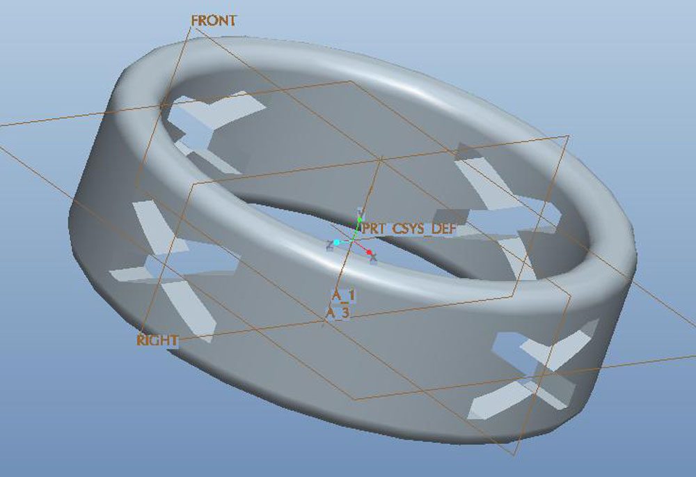
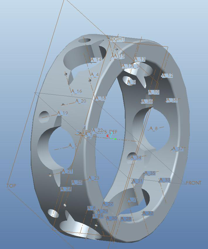
Ring Sample 1
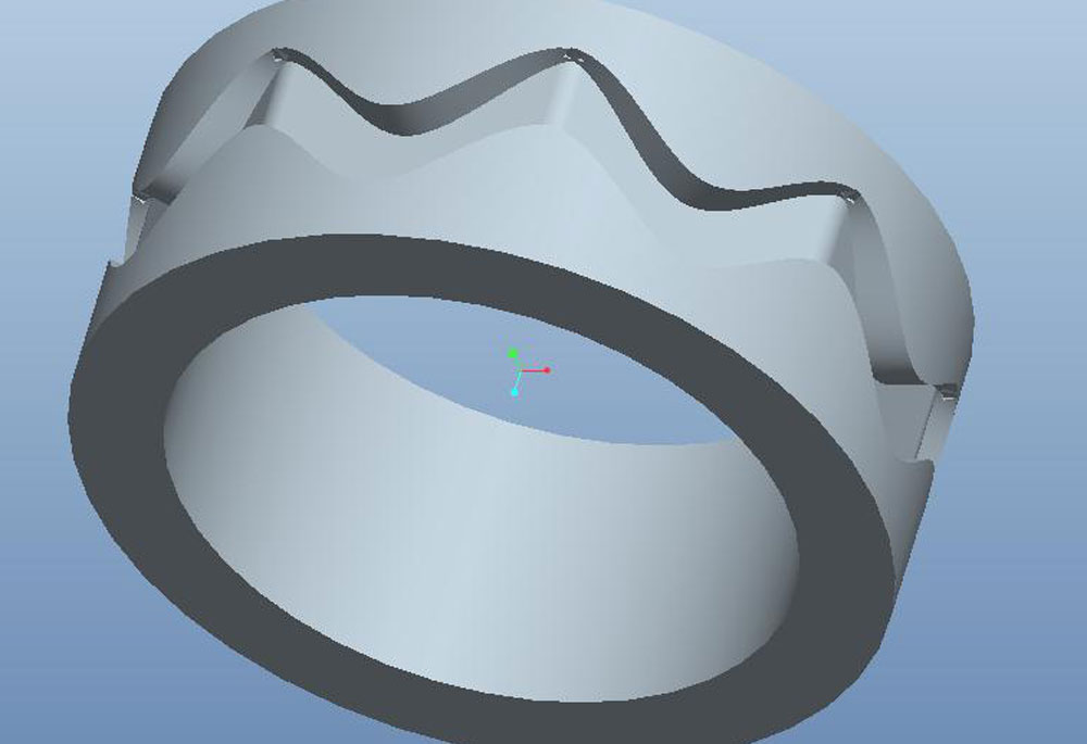
Ring Sample 2
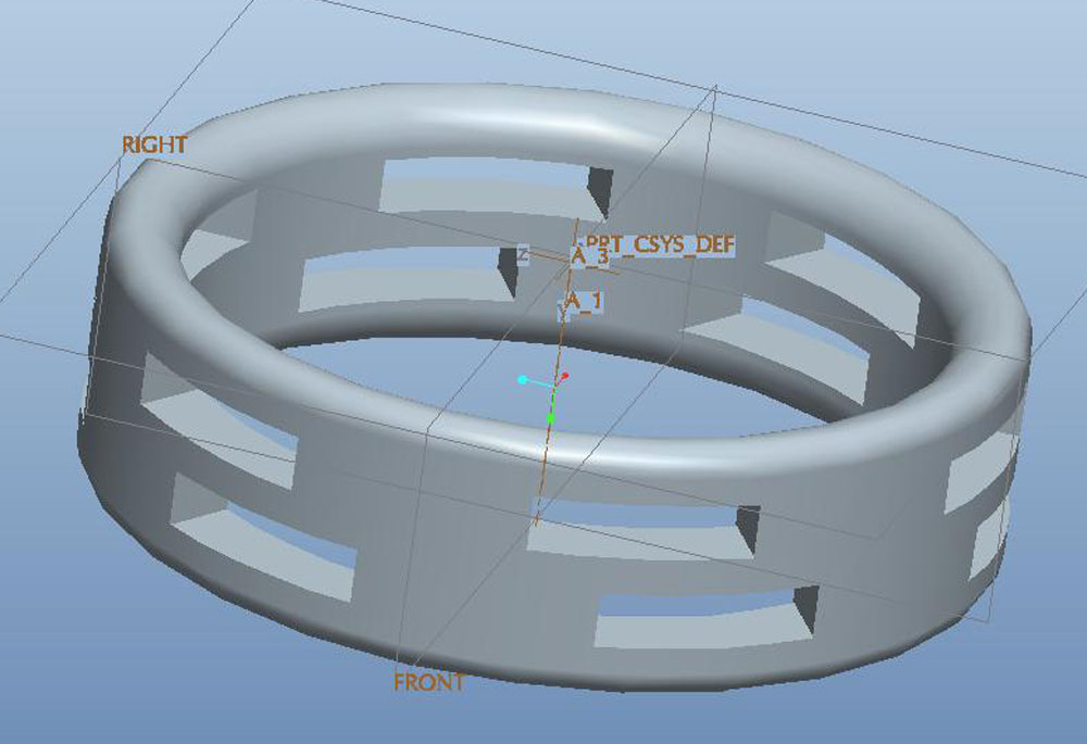
Ring Sample 3
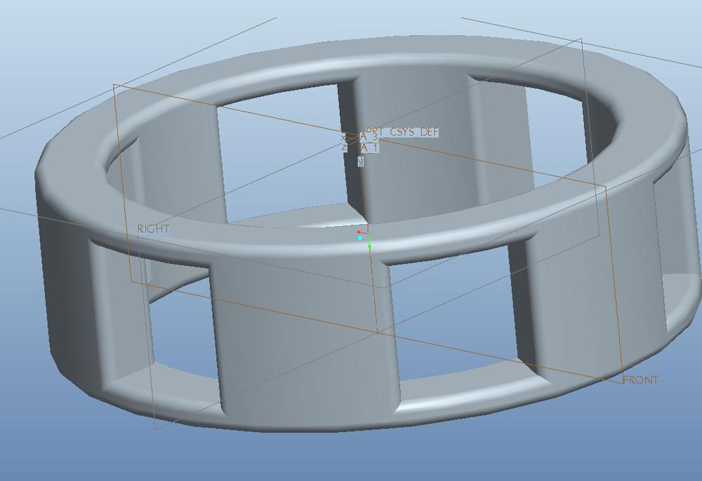
Ring Sample 4
Create/Construct:
With past projects and assignments experience, here are the steps to guide you through this process
- Complete ring tutorial
- List all of the SPICE steps with explanations
- Research and list three sources on ring designs/history
- Sketch 5 Thumbnails and pick the best one
- Sketch a cylindrical orthographic with dimensions with the above paperwork attached and have it marked
- Draw your new custom ring design
- Hand-in your new design with appropriate file formats
- Print your ring (if time permits) and finish
- Create a final drawing file with 2 ortho views, dimensions, isometric, and id note at the bottom
- Hand in all files similar to last two projects.
File names to use for ring tutorial is: j-doe_ring-tut,and for the custom ring use the following name: j-doe_ring-cust
Evaluation:
You will be evaluated based on the completion of the above 10 steps and your final product design.
| Evaluation Breakdown Component Descriptions | Marks |
|---|---|
| Always double check that you have completed all components for full marks. | |
| Ring Tutorial - completed - PRT,PDFu3d, and JPG files | 10 |
| SPICE - design process steps written, including history of the ring | 10 |
| Thumbnails - create 5 filling a full page with notes | 10 |
| Orthographic Sketch - Show final design with dimensions | 10 |
| 3D Model - Final ring design model completed - PRT, PDFu3d, and JPG | 10 |
| 3D Print - Final ring design printed and refined | 10 |
| Ortho Drawing - 2 views, overall & detail dmensions, isometric, and id note | 10 |
Related TDJ2O1 Course for Next Year
Technology Design is key to making great technological marvels. Engineers help us every day with new innovations to make our lives easier, safer, and more fun. This career field is an amazing area to be in with technology exponentially growing. If you are interested in furthering yourself in this direction, the course to take is TDJ2O1. Here are some resource links: