Unit 4: Building Foundation to Finish
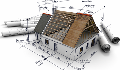
This unit will allow students familiarize themselves to different building construction fields, focus in on ![]() common residential home builds, to build partially constructed structures and work with related materials, and experience first hand construction processes. During this process students will learn about how residential buildings are put together, materials used, and building related standards.
common residential home builds, to build partially constructed structures and work with related materials, and experience first hand construction processes. During this process students will learn about how residential buildings are put together, materials used, and building related standards.
Course Units and Descriptions
Use this table for an overview and navigate to each of the course unit pages.
| Unit | Description |
|---|---|
| Review course outline for more details | |
| 1 | Safety, Shop, and Practice - intro, safety, tools , machines, projects, and reporting |
| 2 | Technical Drawings and Circuit Theory - reading drawings, code, and wiring ccts |
| 3 | Wire Joints, Devices, and Wiring - wire, joints, elect. devices, and wiring methods |
| 4 | Building Foundation to Finish - concrete base, carpentry, electrical, plumbing, and drywall |

Unit Content Activity Quick Links,
Click to Jump to Specific Activity!
- Unit 4, Act. 1: General Construction
- Unit 4, Act. 2: Concrete Foundations
- Unit 4, Act. 3: Wood Framing
- Unit 4, Act. 4: Home Construction Utilities
 Unit 4, Act. 1: General Construction
Situation:
There are many related construction career fields that students can choose to go into and should explore those possibilities. Before focusing in on some specific construction stages/areas, an overview of the whole construction process is an excellent way to see the big picture of how a home is built from start to finish. Looking at materials and how they are used to build residential structures is a great way to introduce students to some of what the construction industry is all about.
Problem/Challenge:

Select and research a specific construction related field and include schooling, job responsibilities and expectations, current and future outlook, and expected wages on a informational page to share with the class. Students will create a presentation slide show, showing ten major steps in home building process with a in detail focus on one selected area of interest. Lastly you will create a sketch showing a sectional view of a single story home showing the basement up to the start of the roof truss with a home that you live in or are very familiar with. Some researched assumptions may be made looking at several typical sectional views of similar construction. You are to show materials labeled , enlarged details, added colour, and descriptive notations.

Investigation/Ideas:
This activity gives students an opportunity to learn about their interested construction related field and also of their peers. The home construction build process has a lot happening, so getting an overview of the ten major steps and then expanding on one area you are interested in and sharing with the rest of the class will allow the class to learn about several areas at the same time. A closer look at typical residential home structure and materials they use and then comparing to your home or one of interest in your circle of interest is a great way to understand how homes are typically built in comparison to specifics that you see or are interested in, and sharing with class to see some of the variants and differences.
Construction Related Career
The first task involves selecting a related field in construction that you may feel interested in and researching details about that area. If you are having trouble deciding on which trade, you could try an Online Employability Skill an Attitude Quiz to help you decide which field might be best suited to look into. Below are some great resource links to assist with finding more information on your selected career field of construction you are interested in.:

- Careers in Construction
- Ontario Civil Construction Careers Institute
- Five Occupations in High Demand
- Workopolis, Current Construction Jobs
- Indeed, Current Construction Jobs
- Build Your Career in Construction
- Wikipedia, Careers in Construction
- Canadian Construction Association
- Canadian Home Builders' Association
- Durham Workforce Authority
- Build Force Canada
- Canadian Apprenticeship Forum
- National Occupational Classification
- College of Trades
- Ontario Job Futures
- Ontario Prospects
- Ontario Colleges
- About trades - Construction
Remember the information is to be on one page (maximum both sides) showing a title, sub titles, key information in different forms such as text, charts, maps, illustrations, and/or images. Images and/or chart should be no more than 50% of page and information must include the following:
- Job title, general description, responsibilities, and salary/wages
- Related skills, interests and values
- Schooling, preparation and requirements
- Future forecast/outlook of field area
- Your resources and where to go for further support

Home Construction Build Process
There are several steps involved in a constructing a home that construction related workers should be aware of. The following resource links can be used to gather the 10 major steps and explanations of what is involved and then selecting the area of interest to further expand in detail what happens and later share with class through a Slideshare presentation:
 Home Construction Process Pkg.
- The Building Process
- Home Construction Process
- Building A Home
- How to Build a House
- Steps to Building a House
- Building Design and Construction Process
- Typical Construction Process
- Construction Process with Time Lapse
- Overview of the Home Construction Process
- Sample Residential Construction Schedule
- A Description of the Home building Process
 Time Lapse of Home Build
- House Construction Documentary
- Building a House - Start to Finish
- Construction of Houses - Timber Frame
This project should be accompanied with 10 major home build stages with a quick explanation and then selecting and explaining that stage in more detail showing a in-depth look of what is involved. You will need a title page, introduction, list with description of each major stage of the construction build process, and then an expanded section on your interested area, a conclusion slide, and a resource slide where you found your information. As this is a presentation, each slide should have a graphic element 30-50% of slide and large bulleted text points.
Sectional Home Sketch
Being aware of the different materials used in home construction, their purpose, and how they interact with each other to form structures and being able to compare with similar structures that are familiar with will give students a deeper understanding of structure materials, how they fit, and their purpose as part of the whole structure. Below are some resources showing common/typical home build sectional view drawings, materials used, their placement, and how they fit as part of the whole structure.
- House Plan Terms
 Single story typical home section view 1
- Single story typical home section view 2
- Single story typical home section view 3
- Typical floor/wall section detail 1
- Typical floor/wall section detail 2
- Two story home section view
Create/Construct:
Three major tasks to complete in this activity include:

- Create a career information page using the handout guide, using a maximum of 1 page both-sides to include text, possible illustration/pictures, and chart/table showing key details of your interested construction related career. Below is a sample PDF and if you want it in DOC format just click on it. Convert or save your DOC Construction Career to a PDF format, then upload to Moodle server on your course Moodle Wiki, (you will need to sign-in to submit your work) so that it may be viewed by your peers and evaluated for marks.
- Create a slide-show presentation outlining 10 major stages of home construction building process, your expanded stage/step in detail to share with the rest of the class.
- Sketch a single story home sectional view of your interest showing all materials and their placement of the foundation, basement, first level, and partial truss/roof.
You are encouraged to use appropriate computer programs that you are familiar with. There are several programs such as Microsoft or Open Office for use with the career and presentation projects, For the sketch creating by hand using graph paper may be helpful, or just use blank paper with a pencil. Each research report paper is designed to allow for two-three periods, so that you can manage your time during class and after school if needed. The home sectional view should represent the home you are familiar with and a picture kept handy would be a great idea to show with your project.
Sample Career Page
Evaluation:
Below is a breakdown of the project sections and what must be evaluated:

| Evaluation Breakdown Component Descriptions | Marks |
|---|---|
| Always double check that you have completed all components for full marks. | |
| Selected Career - see |
20 |
| Home Construction Process - PPT- 10 stages, detailing of 1 area, bullets & images | 30 |
| Home Sectional Sketch - materials, placement, & fit in a single story home | 30 |
Unit 4, Act. 2: Concrete Foundations
Situation:
At the base of all construction, foundations are used to support constructed structures. Exploring this construction process will help students understand the importance and process of concrete foundations.

Problem/Challenge:
Students will explore why foundations are needed and the different types commonly used. They will create their own sample concrete partial wall form in groups of three, mix concrete, pour, and finish for use later with wood structure build sample.
Investigation/Ideas:
Foundation build process, materials used, and how it comes together will help understand the importance of foundations and how they support and distribute building structure loads. Working with concrete, major concepts such as safety, measuring, mixing, and tools are important to know in order to handle properly, create a professional result safely, Some general terms that you should be familiar with are:
- Cement - a grey powder material which with water will harden added mixed aggregates such as sand and rock
- Concrete - a mixture of aggregates such as sand, cement, and small rocks mixed with water which hardens like artificial stone
- Mortar - a material used to fill the gaps between blocks and bind them together
- Caustic - is a substance that can break-down, damage, or destroy other substances
The ![]() Building Concrete Foundations handout, includes related topics: foundations, foundation walls, build process, breakdown foundation section parts, concrete mixing, safety, and basic tools to support students learning of this activity.
Building Concrete Foundations handout, includes related topics: foundations, foundation walls, build process, breakdown foundation section parts, concrete mixing, safety, and basic tools to support students learning of this activity.

Concrete Foundations
Concrete foundations are a necessary building construction component that creates a solid foundation for building up your structure or support for long and lasting base. The following video's cover the process and importance of foundations:
- Types of Footings Residential and Commercial Construction, (2.5 min.)
- Concrete footer part 1, part 2, part 3, part 4
- LA - Building the footing forms, (5.5 min.)
- LA - Pouring footings and stripping forms (6.25 min.)
- How To Animation: Foundation to Framing, (0.75 min.)
- How To Animation: Poured Foundation Wall and Insulated Slab, (1 min.)
- Different Foundation Wall Types, (4.25 min.) - Details written on web site
- 4 Methods of building concrete form work for foundation walls, (2 min.)
- LA - Foundation wall - part 1, part 2, poured, finish-up part 1, part 2, part 3
- Slab Plumbing, (5.5 min.)
- Top 10 Myths in Concrete Construction (17 min.)
- Excerpts from the 1994 Uniform Building Code
Ten Building Stages
- Survey and steaks done by a surveyor using building plans will determine appropriate distances from property line, where the building corners are located using stakes.
- Excavation removes earth inside of those stakes a depth based on building plans done by design engineer.
- The top of the footings must be below the winter frost line to prevent concrete from cracking and shifting when the ground thaws. Wood forms are used to hold the poured concrete pathways to create the building foundation to support the foundation walls and also include re-bar to strengthen tensile load demands. Foundations are always wider than the foundation walls to anchor and spread the load and it is common to have additional footings inside the building perimeter to support load bearing beams and walls.
- Prior to the slab (sub-slab work) being poured plumbing such as water and sewage lines are run under the footings and located appropriately. Underground electrical service will also have to be considered during the wall foundation process. Radiant heating which needs flex pipe inside concrete slab may also be needed in basement slab if the design plan calls for it.
- Foundation drainage is placed outside and above foundation using filter cloth, gravel, and weeping tile made up of 4" plastic hole-punched corrugated-plastic drainage pipe to prevent water pooling and possible basement flooding.
- Foundation walls generally are poured concrete, but may be built using cinder block, and then filled with concrete, both of which will also use re-bar also.
- Predetermined locations of 1/2"wall anchor bolts embedded 7" into top of wall foundation to hold down sill plate (1st floor and exterior walls i.e. house) to foundation wall usually no more than 6' apart while beam pockets also located top of foundation walls hold I beams running across length of home also supported internal foundation and column supports.
- Exterior walls are waterproofed with a special sealant and/or plastic wrap below grade to help stop water leaking into basement. Exterior insulation such as Styrofoam is also a consideration which design may require.
- The 4" basement slab is poured above and inside the foundation/foundation walls and will help stabilize the base of the walls.
- Backfill is put back against the waterproofed walls and on top of the filter cloth, gravel, and weeping tile drainage system.
The following are related videos using concrete to build some amazing structures:
- Extreme Engineering - Mega Structures - Build it Bigger
- Toronto's CN Tower completed by The Foundation Company of Canada
- Constructing Tallest Building in The World - Burj Khalifa - Documentary
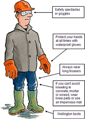
Safety
Working with cement has some safety concerns. It is important to wear rubber coated gloves and eye protection. The following precautions must be kept in mind when working with concrete and cement.
- Contact with wet concrete, mortar, cement or cement mixtures can cause skin irritation, severe chemical burns, and/or serious eye injuries
- Avoid contact with eyes and skin
- Wear waterproof/rubber gloves, long-sleeved shirt, full-length pants, and eye protection
- Wash any wet concrete, mortar, cement, or cement mixtures from your skin immediately
- Seek immediate medical attention if you have persistent or severe discomfort
- In case of eye contact, flush with plenty of water for at least 15 minutes and consult a physician immediately
- Wear a well made respirator while handling dry cement dust. Do not breath in air-born cement dust or other fine particles
The following resources show more detailed information on all safety concerns when working with cement and concrete.
- Working safely with concrete
- Cement hazards, health risks, and precautions
- Concrete safety tips
- Material Safety Data Sheet (MSDS)
- Portland cement safety precautions and protection
- Skin safety with cement and concrete
- Laying the groundwork: concrete construction safety
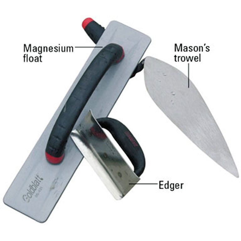
Typical Tools
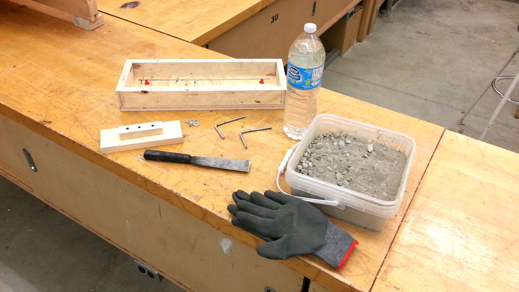
Below are some links showing typical tools that are commonly used with concrete depending on the extent of work needed. For our project we will need a hammer, 2" scraper, concrete mixing container, floater, along with our dry mix concrete, water, and safety protection equipment. Here are some links to more common tools that are used when working with concrete in different situations:
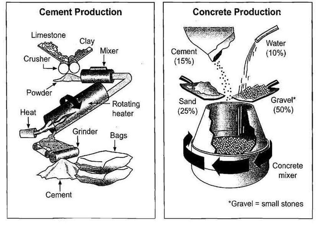
Cement, Concrete, and the Mixing Process
Concrete can be purchased pre-mixed dry or wet. It can also be acquired by it's separate aggregates such as cement, sand, gravel, and with the addition of water will allow you to make formed concrete. More information can be found on the ![]() Building Concrete Foundations handout and links below:
Building Concrete Foundations handout and links below:
- All About Cement
- How to Properly Mix Concrete
- Difference between concrete and cement
- Cement, how it"s made
- Concrete, how it"s made
- Quikrete Guides to Concrete
- Fundamentals of Quality Concrete
- All about re-bar
- Tying reinforcing steel bars (re-bar)
Create/Construct:

First read the ![]() Building Concrete Foundations handout, fill in the blanks for illustrations, and answer the review questions.
Building Concrete Foundations handout, fill in the blanks for illustrations, and answer the review questions.
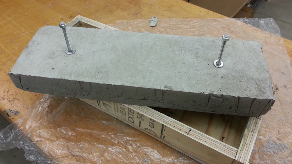
Next you will have the opportunity to create a sample portion of a foundation wall by using dry pre-mix of concrete. You must have your form together, have all your hardware ready, and familiar with the concrete mixing, pouring, and finishing concrete process before starting the actual concrete and water mix. It must also be done with at least 20 - 30 minutes of practical time available in order to finish this part of the project to the end. As you know once you start mixing your concrete, the curing process begins and you have limited time to pour, finish, and set the concrete. Here are the ![]() major steps you should follow:
major steps you should follow:
Creating Wall Foundation Form Process
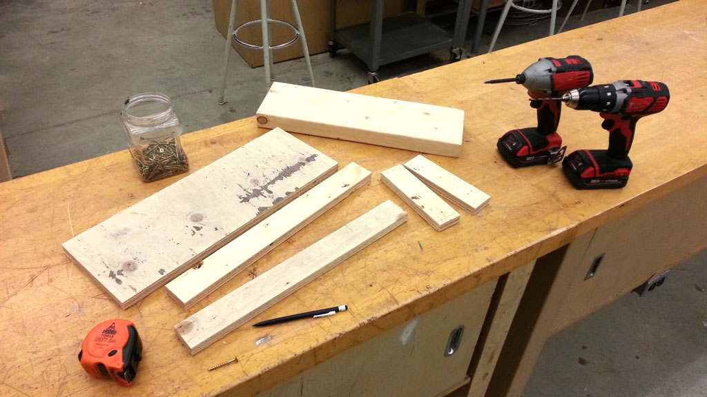
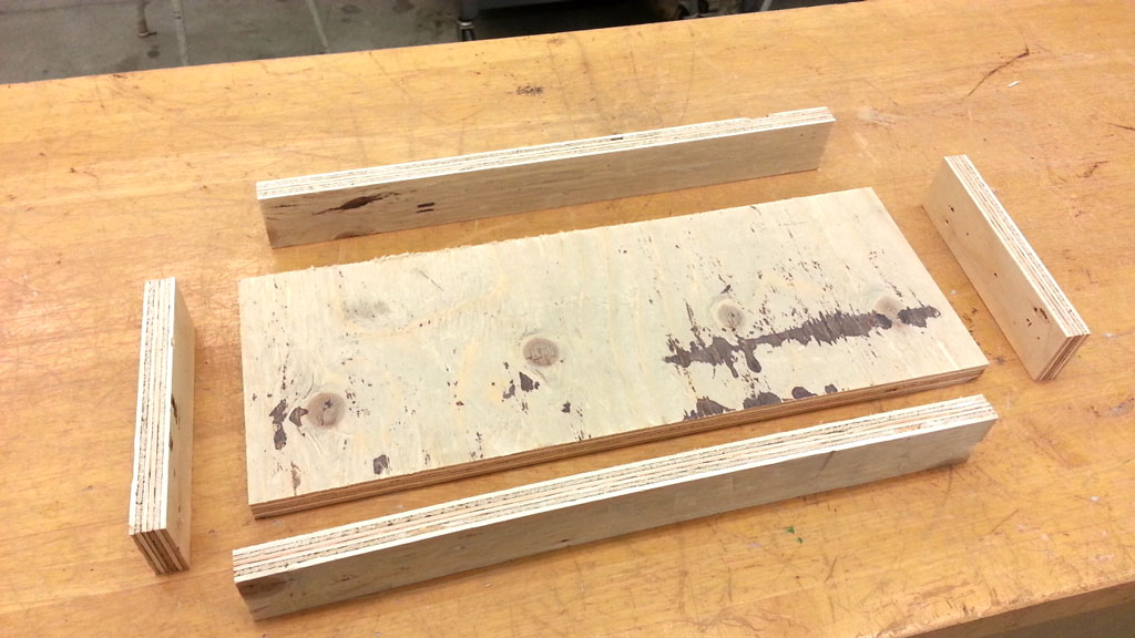
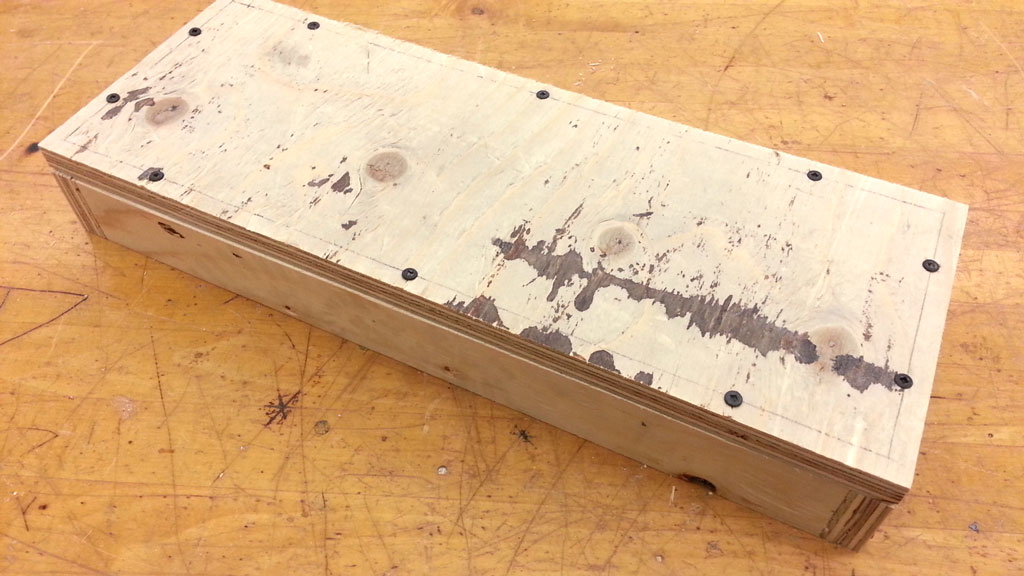
- Using 1/2" for the bottom piece and 3/4" plywood for the sides, figure out the best way to make the best use of your cuts to minimize waste, i.e. layout and plan your cuts
- You will need to make a form the size of 17.5" long by 5.5" wide by 2" high and screw together the sides and then the bottom to the sides
- Using your circular saw, clamps, make straight accurate cuts for the bottom and side pieces, use the power miter saw to cut lengths
- Use a 2 by 6 cut to 17.5" to shape the edges, then mark and pre-drill the holes to prevent splitting, then use screw gun to screw 2 screws per corner
- Screw bottom into sides using two screws on the width pieces and 3 for the length pieces
Foundation Form Step 1
Foundation Form Step 2
Foundation Form Step 3

Foundation Form Step 4
Form Hardware, Wall Anchors, and Plastic Preparation
- For re-bar, use the 3/16" steel rod bent in a smaller rectangle 16 by 3" rectangle
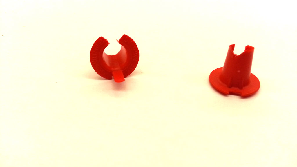
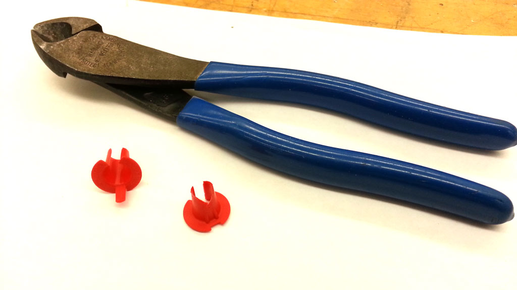
- Take four electrical anti-shorts and use diagonal/side cutters to trim nib off and create a groove to support mini re-bar just made
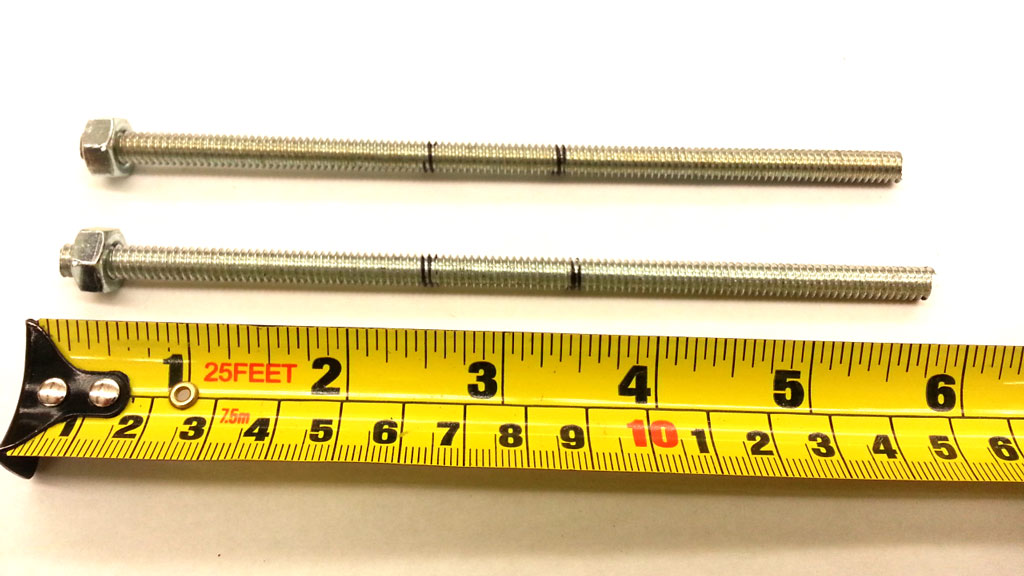
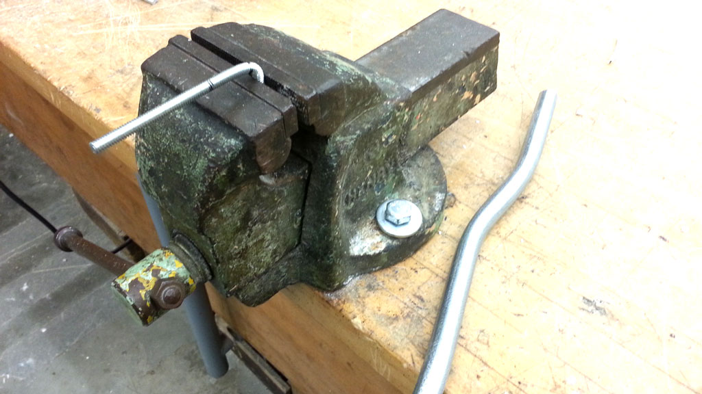
- Cut with hacksaw two 6" lengths of 1/4 -20"galvanized all thread and then carefully bend 90 degrees at about half way for use as wall anchors
Form Hardware 1
Form Hardware 2
Form Hardware 3
Form Hardware 4
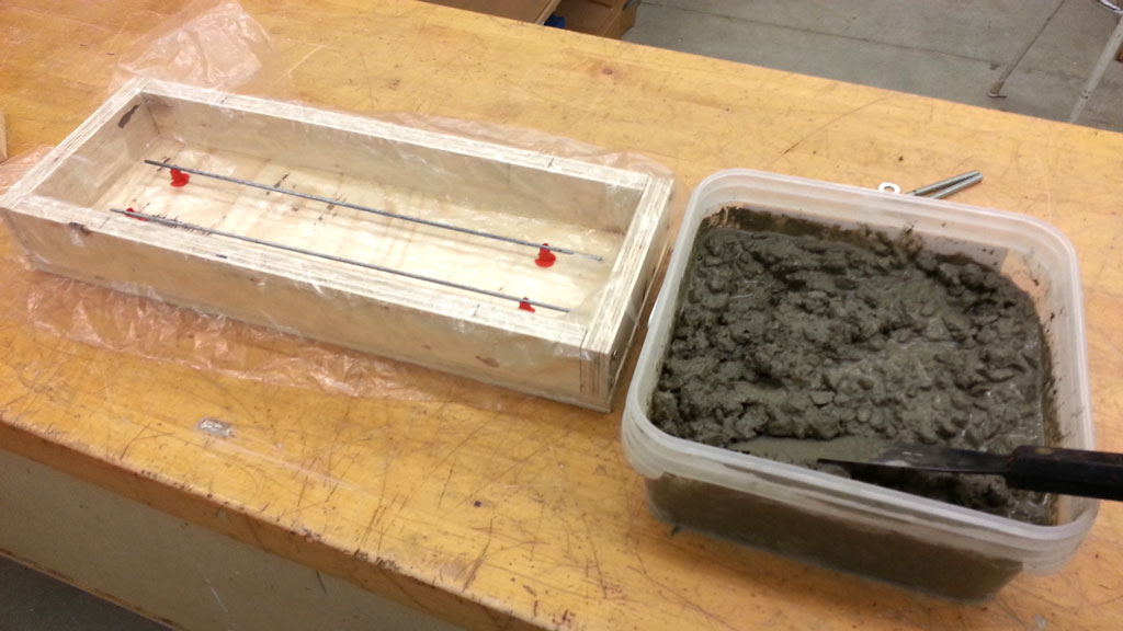
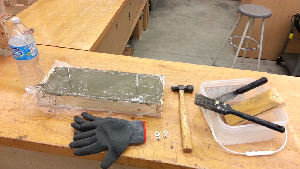
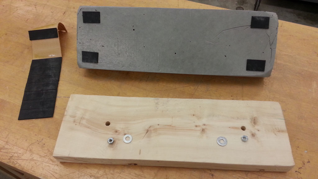
Mixing, Pouring, and Finishing Concrete Wall Foundation-sample Process
- First get your safety glasses, rubber gloves, and ensure you have long sleeved shirt and long pants on
- Ensure your form is ready for the pour of the cement, re-bar is installed, wall anchors are ready, mixing container, cement/concrete tools ready to go, and you have enough time to complete the whole process - half a period
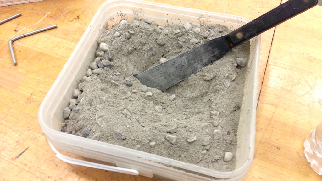
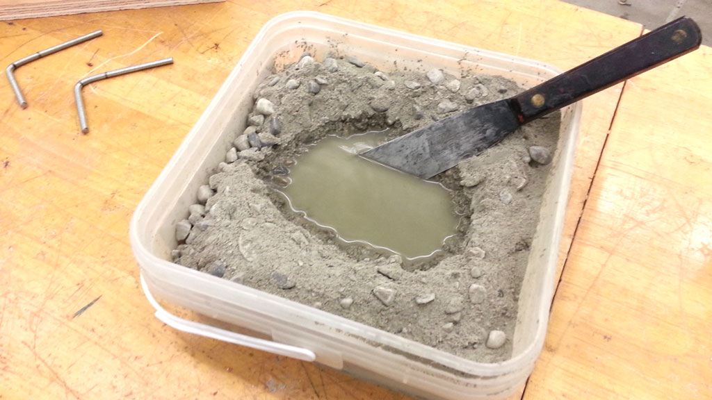
- You will need to enough concrete to fill your form 17.5" * 5.5" * 2" which is about 2.75" deep in supplied 9" * 9" plastic nail container (which we will be using to mix the concrete in) and also half a liter of water
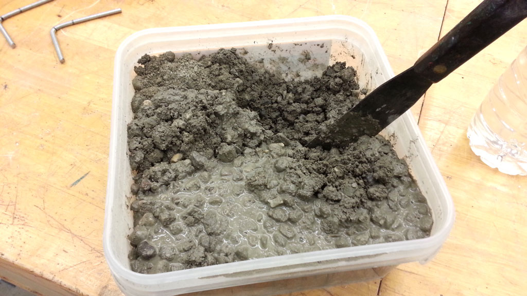
- Pour pre-concrete mix into mix container to 2.75" high, make a small cavity in the centre and pour 300 ml of water in and mix with small shovel or scraper
- Mix until concrete mix is pasty wet and uniform
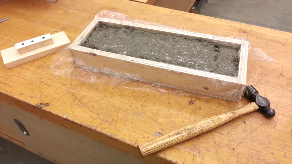
- Pour into form with plastic and mini re-bar in place, being careful to not knock down support chairs and mini re-bar down
- Using hammer, lightly bang the sides of your form to settle the concrete into the form tighter
- Use floater when concrete is topped up to level and finish the top surface of concrete
- Accurately place the two 1/4" wall anchors into position - centre and straight about 3.5" in from the sides and ends, then clean up top of concrete surface finish
- Finish by putting group initials neatly and lightly and clean up area, your tools, and mixing container
Concrete Mix & Finish 1
Concrete Mix & Finish 2
Concrete Mix & Finish 3
Concrete Mix & Finish 4
Concrete Mix & Finish 5
Concrete Mix & Finish 6
Concrete Mix & Finish 7
Concrete Mix & Finish 8
Evaluation:
When working on the foundation sample in your group of three, you will be marked on your participation, effort, work ethics, proper techniques, teamwork,, and process. Below is a breakdown of the project sections and what will be evaluated:
| Evaluation Breakdown Component Descriptions | Marks |
|---|---|
| Always double check that you have completed all components for full marks. | |
| Foundation Handout - |
30 |
| Foundation Form - 17.5" * 5.5" * 2" screwed together, tight accurate fit, with hardware ready | 20 |
| Concrete Mix, Pour, & Finish- amount, process, re-bar & anchors, finish and clean-up | 20 |
| Dynamic Feedback - |
10 |
Unit 4, Act. 3: Wood Framing 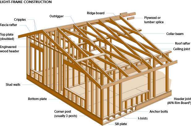
Situation:
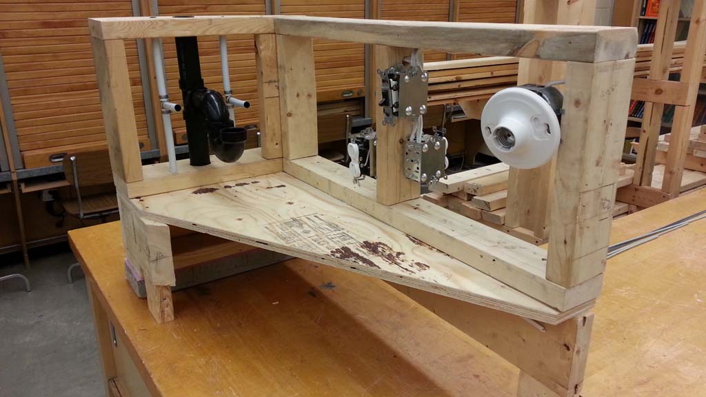
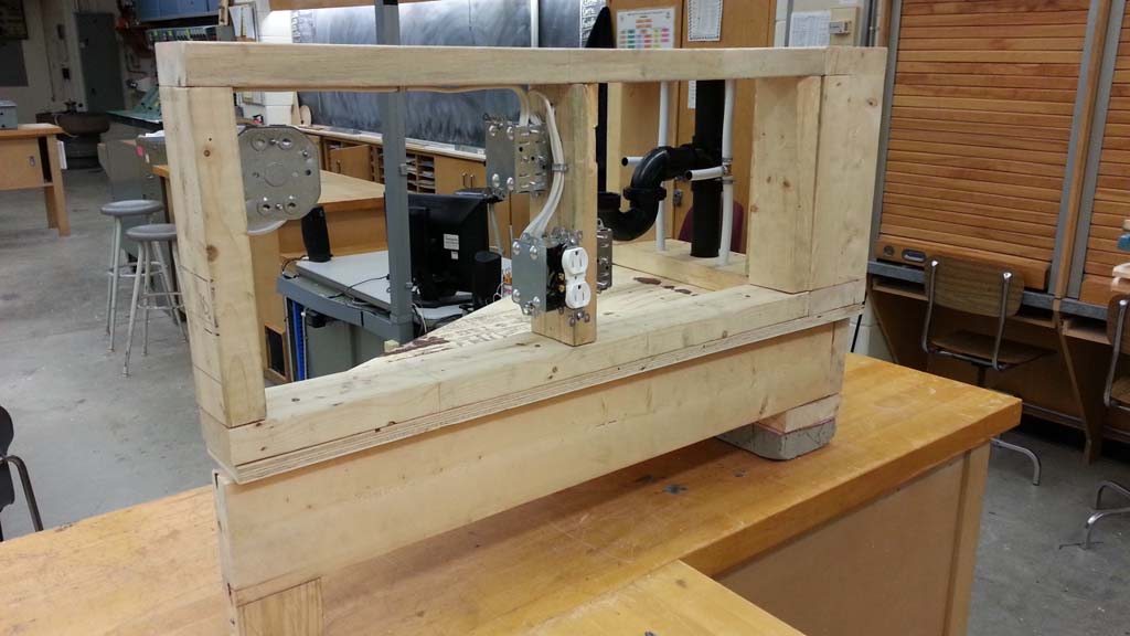
At the heart of all construction is the frame of the building. Using one of the most versatile natural materials - wood, framing in your structure can create the shell of your partial building sample structure. Having created a sample concrete foundation wall, students can use this as part of their build to construct and build a partial build sample
Problem/Challenge:
Students will explore different wood structure framing components, tools, and methods. Students will continue to build on top of their foundation a partial wall sample that will include sill plate, rim joist, floor joist, sub floor, exterior and interior walls as part of their sample build..
Investigation/Ideas:
General Introduction
Some of the major areas to review may include terminology, safety, building code, types of framing, wall components and construction, sub floor construction, related tools, The following general links can be used to review further details about wood framing process, methods, and details.
- Wiki frame construction
- Home time construction framing
- AWC- codes & standards
- Three wood framing methods
- Frame construction walls, rel. PDF
- The future of framing rel. PDF
- Related terms and definitions
- Top 10 framing errors
- CWC -overview of the building Code
- Ontario Building Code official site
- Wood frame envelopes
- Wood frame construction guide
- Conventional wood frame construction
- Time lapse home const., (2 min.)
- How its made - wood const., (5 min.)
- Framing and building a wall, (5.75 min.)
- Const. of houses, (28.25 min.)
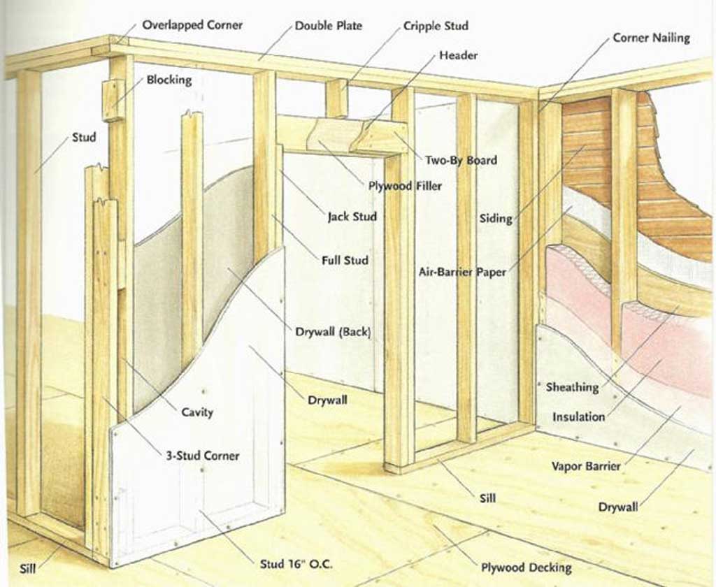
Related Terminology
There are a lot of related terms related to the rough carpentry/framing industry used to communicate and understand the frame builds:
- Bottom plate (also know as base or sole) plate - horizontal piece found as the base/bottom of the wall supporting all the studs
- Cripple stud - vertical frame member above or below a header or window lintel
- Face-nail - nailing 90 degrees to the surface of the wood you are nailing
- Joists - run horizontal to support floors
- Header - horizontal support span in a wall, usually above a door or window
- Sill or lintel - is the lower horizontal span support piece below the window
- Sill plate - wood that is anchored to the foundation wall, providing a nailing surface for other frame components
- Stud - vertical members making up walls
- Sub floor - usually the plywood supported by floor joists
- Toe nailing - nailing on a 45 degree angle through to another component
- Top plate - horizontal piece found at the top of the wall

Wood Framing and Construction Safety
There are many safety aspects to be aware of such as personal protective equipment, proper construction methods, proper use of tools, following building codes, fire safety, WHIMS, your rights as a worker, and work hazards. Building codes regulate items such as ceiling heights, door openings, width of hallways, etc to make living area built safe for the owner.
Carpentry Tools
There are many tools used in the carpentry trade and carpenters working on special jobs may have specific tools related to the task to complete. Some of the general tools you will most likely use are as follows:
- Framing square - for squaring up larger builds
- Speed square - multiple uses such as squaring smaller project, circular saw guide, and pitch
- Framing hammer (20 oz) - used to nail framing together
- Carpenter's level - check if work is level/straight
- Carpenter's pencil - marking and layout
- Chalk line - creating straight lines fast for layout
- 25 foot tape measure - measuring
- Plumb bob - weighted string for vertical
- Sledge hammer - demolition
- Portable circular saw - general wood cutting
- Portable mitre saw - wood cross-cutting
- Reciprocating saw - tight corner cutting
- Power drill - creating holes
- Power screwdriver - screwing different bits
- Pneumatic nailer - air assisted nail gun for faster nailing
- Ladders - to access higher or lower levels of work place
- Scaffolding - create higher working platform to work from
Wall Frame Construction
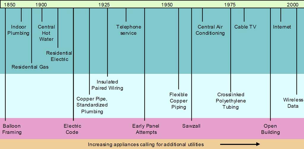
There are three main types of framing called; balloon framing, platform framing, and advanced framing. Balloon framing was an older framing used back in the 19 century up till the 1950's which uses long continuous studs that run from the sill plate to top plate with intermediate floor levels nailed into them. Platform framing is commonly used now in which floor joists rest on the sill plate or on top of a stud wall allowing for separate platform walls. Advanced framing, developed in the 1960's also called optimum value engineering (OVE) is a type of platform framing that makes better use of lumber and resulting in using less and saving money.
It is important when building walls that they are square, leveled, and plumb (straight vertically) otherwise the wall will end up crooked. Sub floor construction includes setting up sill plates by drilling holes to fit over wall anchors with sill gasket between the concrete foundation wall and the pressure treated sill plate. Rim joists sit on the sill plate and both support the floor joists. Beam pockets in the concrete foundation wall are also used on larger homes so joists can span further distances as a whole. Floor joists are usually 16" O.C. apart with bridging and sub floor screwed onto the joists. Walls are built usually on the sub floor with the top and bottom plates with 16" O.C. studs and then raised up into place. Doorways and windows are supported above with headers to spread the load and support the intended wall component. Wall corners are blocked in to allow drywall to have wood to screw down on, in the corners. Here are two more wall illustrations showing similar information in a different way:
Create/Construct:
Complete the ![]() Construction Framing Handout to familiarize yourself with the rough carpentry trade and related information. For the practical part of this project you will be following steps below to create a portion of an exterior wall and one internal wall on a partial sub-floor. Although metric is a standard in Canada, imperial measurement will be used as a lot of building standards are based on common imperial measurements, commonly used in industry. Having some math experience, familiarity with the fractional inch tape measure, and
Construction Framing Handout to familiarize yourself with the rough carpentry trade and related information. For the practical part of this project you will be following steps below to create a portion of an exterior wall and one internal wall on a partial sub-floor. Although metric is a standard in Canada, imperial measurement will be used as a lot of building standards are based on common imperial measurements, commonly used in industry. Having some math experience, familiarity with the fractional inch tape measure, and ![]() working with fractions with an inch is important to know. When ever possible, use smaller material pieces to fit project requirements and/or cut to reduce waste similar to example in sample 7B below. Click here to download print PDF version of steps below.
working with fractions with an inch is important to know. When ever possible, use smaller material pieces to fit project requirements and/or cut to reduce waste similar to example in sample 7B below. Click here to download print PDF version of steps below.
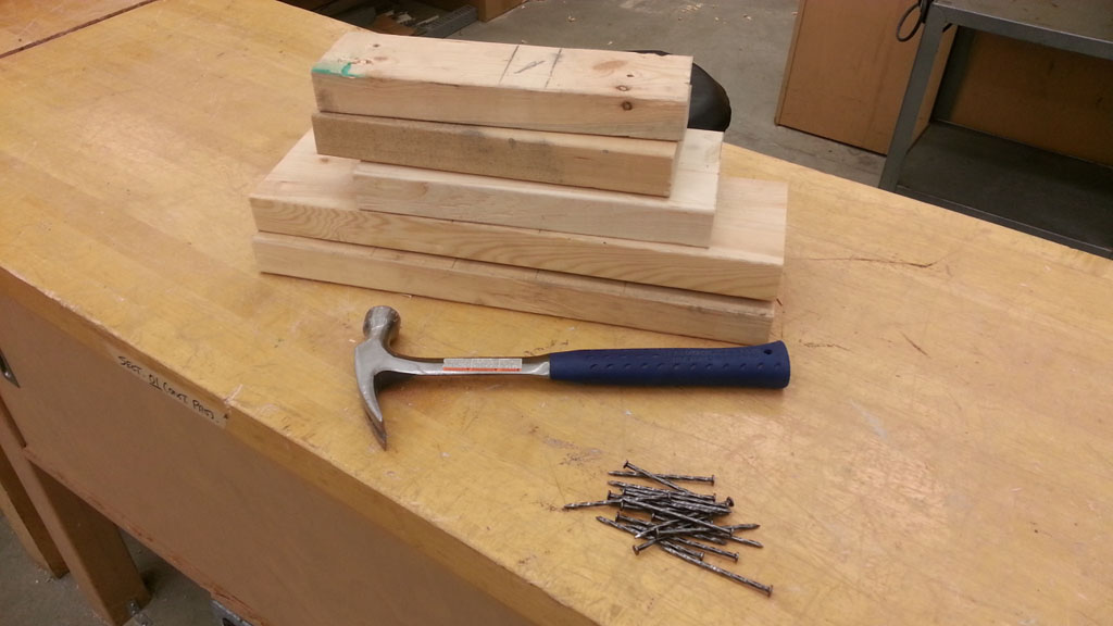
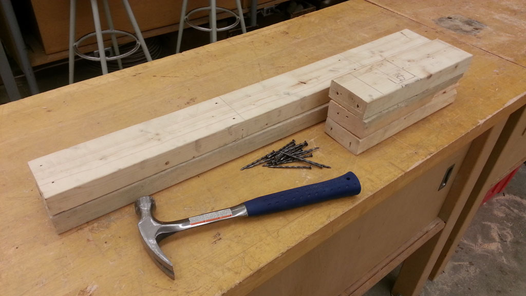
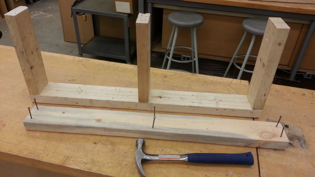
Wall Foundation & Sub Floor - Cutting up the Pieces
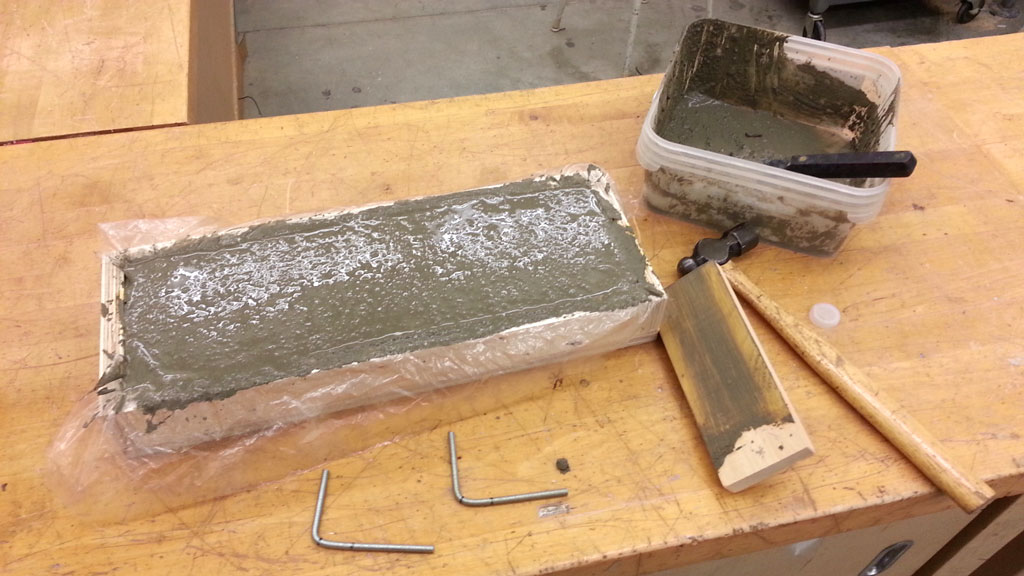
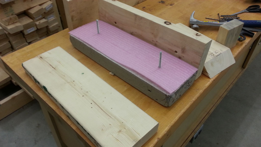
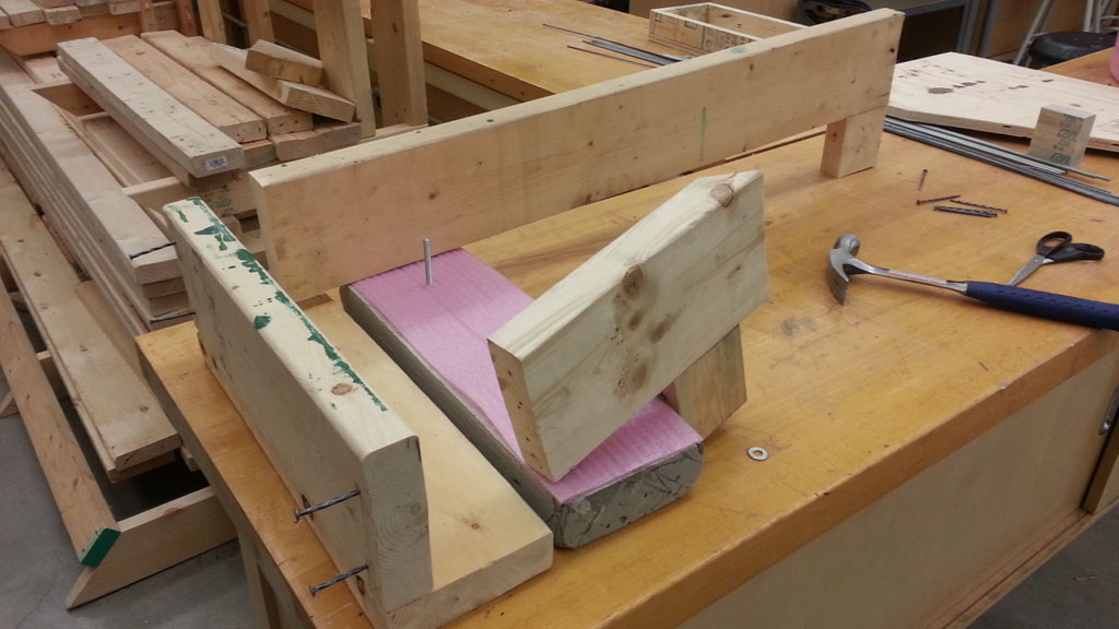
- Form removal (see samples 1 & 2) - Remove your sample foundation wall top piece from your form by removing screws from edges and bottom and put back, take plastic off, add rubber feet by cutting provided rubber mounts in half and attach to bottom four corners, using black permanent marker put group names on narrow edge, and clean-up your area (your form should be 5.5" by 17.5" by 2" with anchor bolts 2 to 2.5" above concrete top)
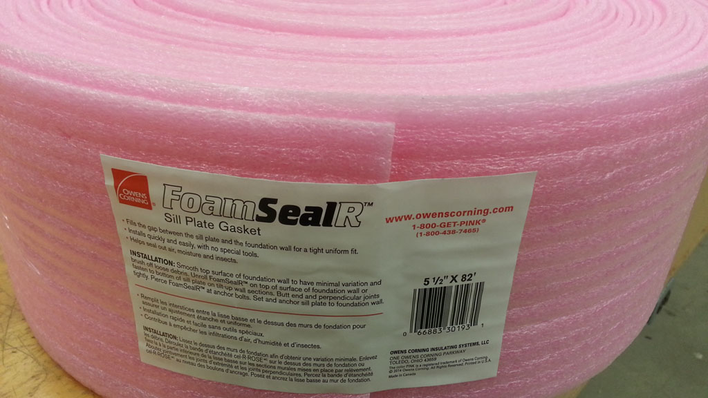
- Sill plate (see sample 2 & 3) - cut a 2*6*1.5" framing board (2*6) 17.5" long, drill 1/4" clearance holes to align with wall anchors/concrete wall foundation top, and cut 17.5" piece of the pink foam sill plate gasket to put between top of foundation wall and sill plate
- Rim joist (see sample 4) - cut another 2*6 17.5" long to later attach to floor joists
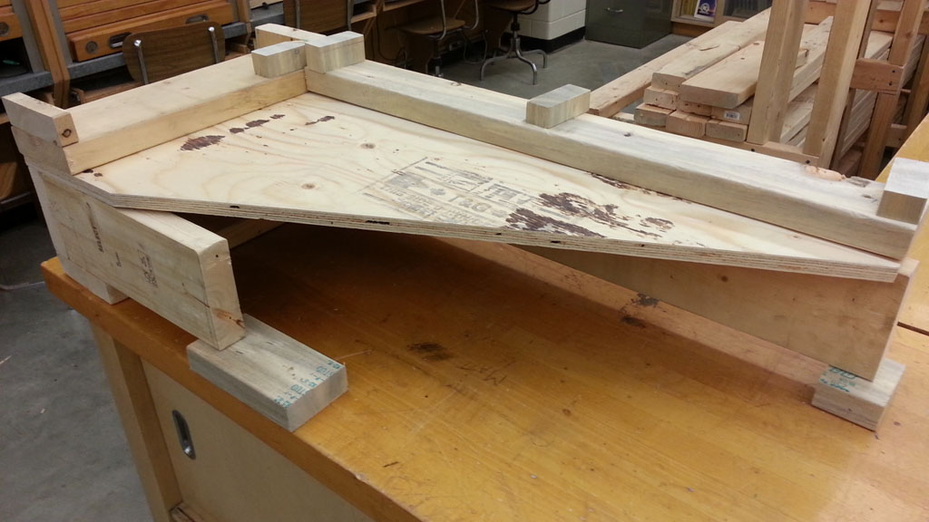
- Floor joist (see sample 5-6) - cut two 2*6's, one at 37.5" long, and the other about 8" to be later cut on a compound 45° angle to match plywood sub floor diagonal cut
- Sub floor (see sample 7-8) - minimize waste of plywood by laying out and cutting a 3/4" plywood standard sheet 22*47"and then cutting on the diagonal (use straight edge and clamps for clean cuts) to be left with two 8*3.5" waste pieces, see step 7b for a graphic link explanation
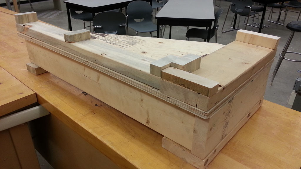
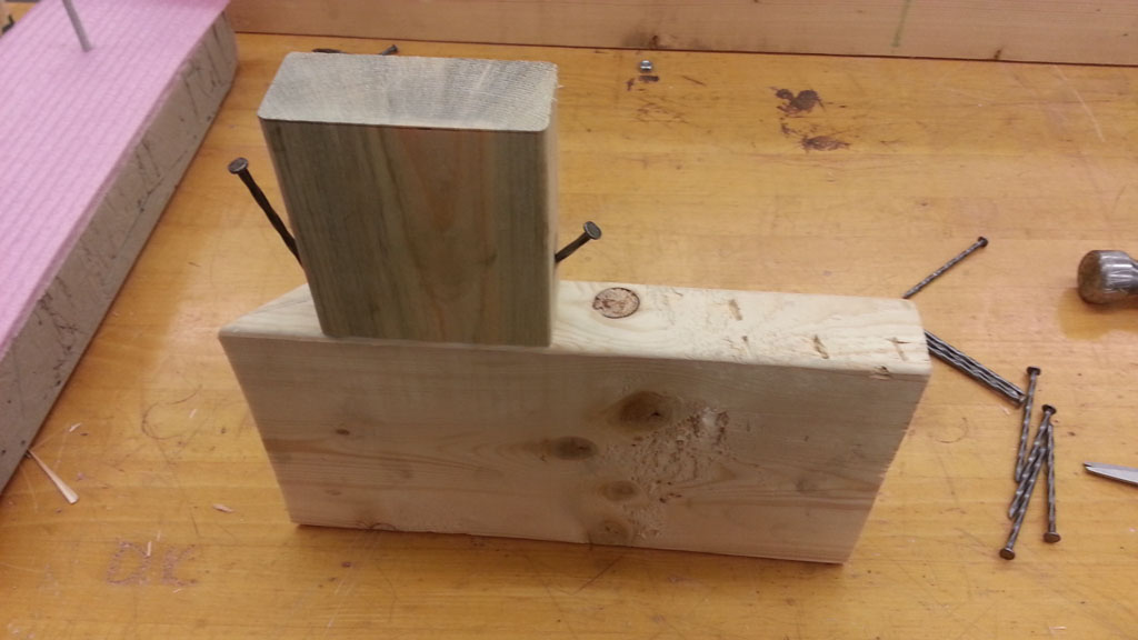
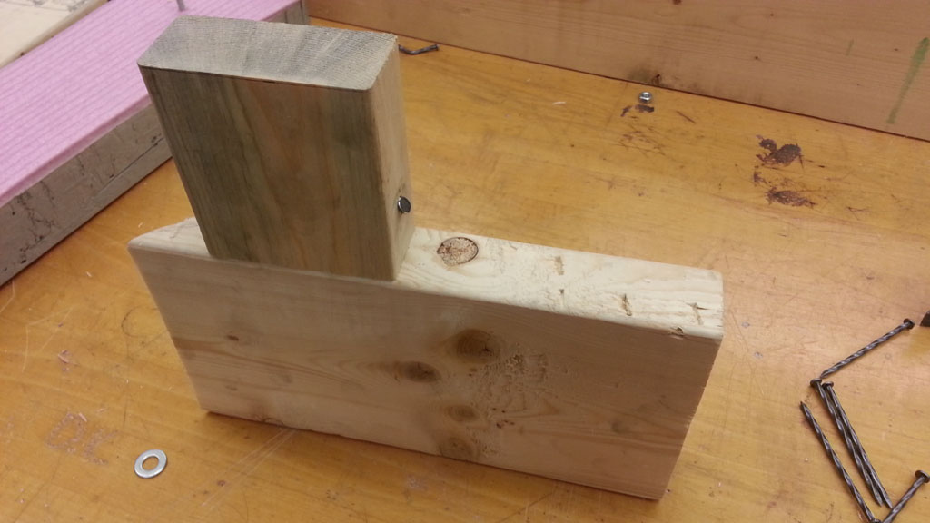
- Base exterior wall plate (see samples 5-6) - Cut 2*6 18.5" long
- Base interior wall plate (see samples 5-6) - cut 2*4, 33.5" (39" full length minus base exterior wall plate thickness 5.5")
- Testing fit (see sample 5-6) - Put all your pieces together including your concrete foundation wall, using a couple of temporary blocks under the ends of the floor joists to ensure all parts fit together (note the sample wall studs you will be placing later in this project)
W.F. sample 1
W.F. sample 2
W.F. sample 3
W.F. sample 4
W.F. sample 5
W.F. sample 6
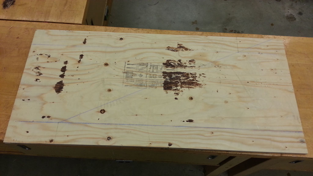
W.F. sample 7, 7B

W.F. sample 8
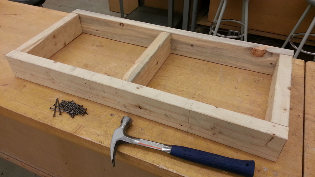
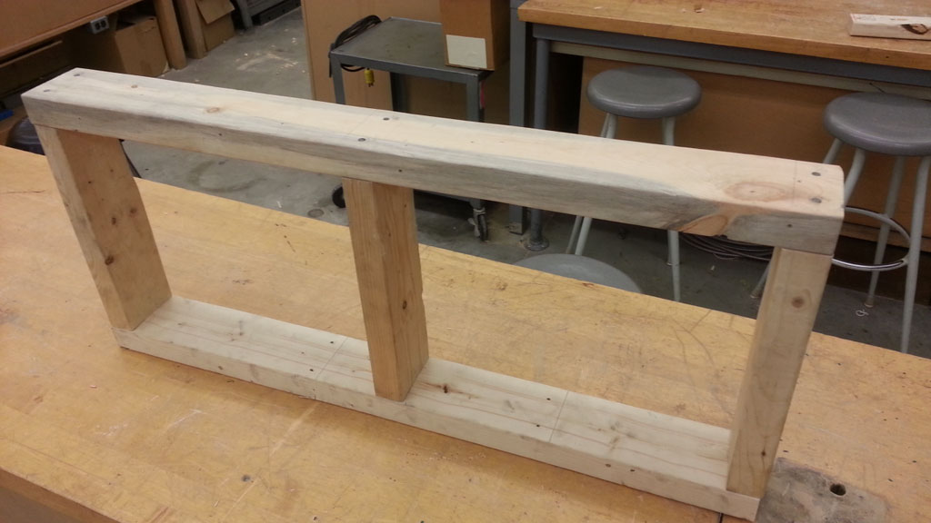
Wall Foundation & Sub Floor - Putting the Pieces Together
- Floor joists stands, (see sample 9-11) - measure the height needed to support both joist ends, the short and long one, cut two 2*4's that length and toenail both to bottom of each joist for joist support (Tip - be careful to not split the wood, and use a nail anchor to prevent wood sliding)
- Sill to rim and floor joist, (see sample 12-14) - nail rim joist to sill plate from below (normally toe nailed) with three nails and put starter nails in for both floor joists, then flip upside down and put two starter nails into bottom of sill plate and use carpenters square to ensure floor joists are 90° from rim joist, then finish hammering nail in from bottom of sill plate, then finish hammering in rim joist nails into floor joist, then do the same for the other joist
- Sub floor to rim and floor joist, (see sample 5 for sample visual) - using the black floor screws, use about 6 to screw sub floor to rim and floor joist making sure plywood overlaps the straight long edge while the other two straight edges are flush
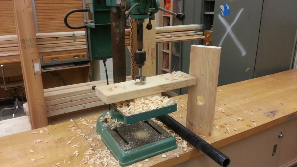
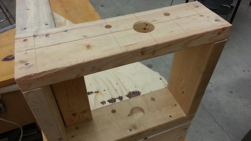
- 2*6 Base/top exterior wall plate plumbing layout, (see sample 15-18) - layout with pencil where wall studs are, and corner 2*4 corner blocking, then find mid point between them and mark centre (should be half of 5.5") for the 1.5" drain pipe, then measure over 3" either side for hot and cold 1/2" pex flex pipe centres and cross mark 1" from inside edge, then cut a second 2*6, 18.5" for your exterior top wall plate and layout the same
- 2*6 Base/top exterior wall plate plumbing hole cutting, (see sample 15-18) - for the top plate you are to drill right through and for the base plate only drill 3/4" into the top, for the drain pipe which you will drill a 1-7/8" using a Forstner bit, and for the two 1/2" water feed pex pipes use a 5/8" spade bit (also commonly known as a speed bit)
W.F. sample 9
W.F. sample 10
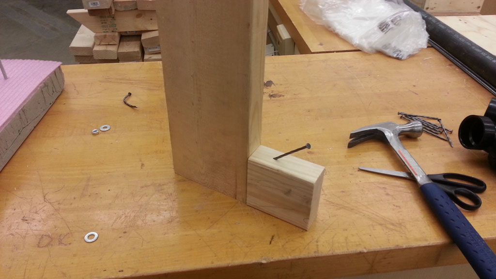
W.F. sample 11
W.F. sample 12
W.F. sample 13
W.F. sample 14
W.F. sample 15
W.F. sample 16
W.F. sample 17
W.F. sample 18
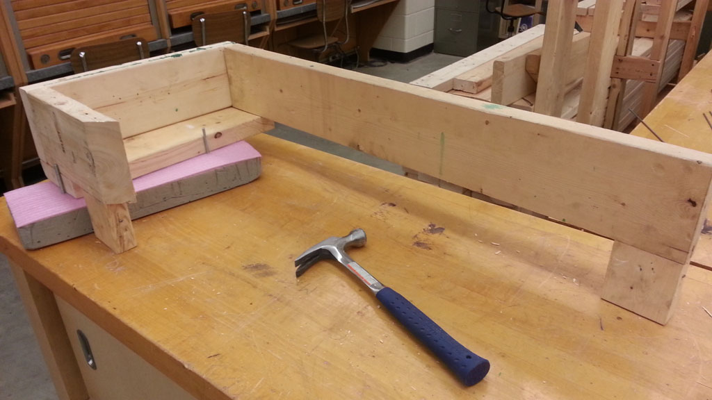
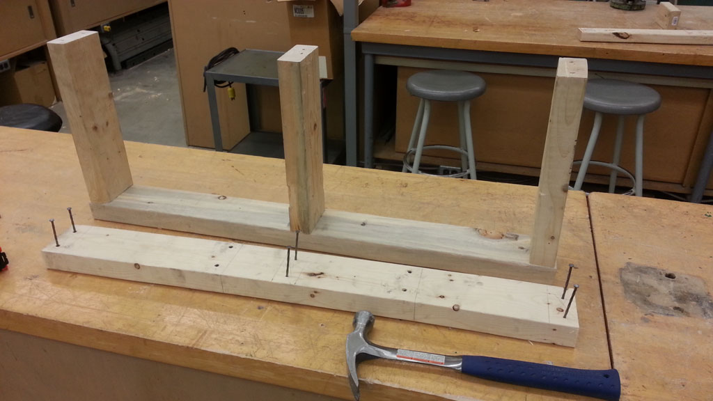
Creating the Partial Wall Frames
- Wall frame pieces, (see sample 19-21) - cut your 2nd interior wall top plate also 33.5", you will need 4 2*4 wall studs with a sample model length for this project of 12" each, and two 2*6 exterior wall studs also 12" long
- 2*4 Framed wall layout, (see sample 22-25) - starting with the 2*4 wall place your pieces together and ensure everything fits, then take both the top and bottom plate and mark where the studs will be going, so you know exactly where the studs are located and where the two nails per stud are going with studs as a standard, 16" apart OC (on-centre)
- 2*4 Framed wall nailed together, (see sample 23-25) - either take top or base plate and start nails where studs are, then line up studs and nail them in place, then take the other wall plate and do the same carefully nailing each piece accurately
- 2*6 Framed wall, see sample 20 and 28) - following similar steps in 2 and 3, layout the two 2*6 studs and the 2*4 corner block, then nail into place ensuring the plumbing holes line up
- Walls to sub floor, (see sample 26-28) - square up walls, then nail down both the 2*6 and 2*4 base wall plates down to the sub floor and joists, then toenail the top corner wall plates together where they meet
W.F. sample 19
W.F. sample 20
W.F. sample 21
W.F. sample 22
W.F. sample 23
W.F. sample 24
W.F. sample 25
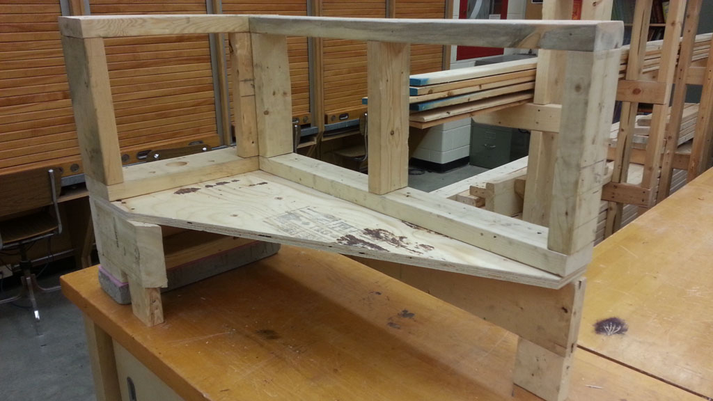
W.F. sample 26
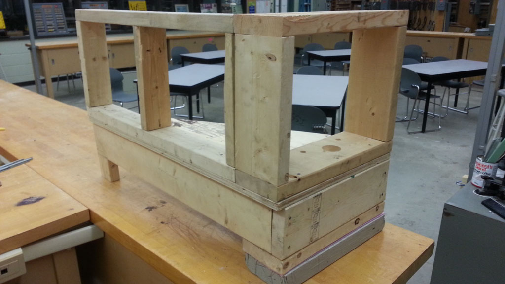
W.F. sample 27
W.F. sample 28
Evaluation:
When working on the framing wall sample in your groups of three, you will be marked on your knowledge, steps taken, participation, effort, teamwork, progress, and process. Using the weekly ![]() task report will allow you individually to track and record your progress daily, get initialed by instructor, and earn marks upon submission at the end of each week. Below is a breakdown of the project sections and what will be evaluated:
task report will allow you individually to track and record your progress daily, get initialed by instructor, and earn marks upon submission at the end of each week. Below is a breakdown of the project sections and what will be evaluated:
| Evaluation Breakdown Component Descriptions | Marks |
|---|---|
| Always double check that you have completed all components for full marks. | |
| Framing Handout - |
30 |
| Group Wood Framing - process of layout, cuts, nailing, fit, square/plumb, and group work | 50 |
| Individual Task Reports - |
~ |
Unit 4, Act. 4: Home Construction Utilities
Situation:
With a sample foundation wall, sub floor, and two walls framed in, installation of utilities such as plumbing, drainage, electrical, ventilation, etc. are important parts of a homes operation.
Problem/Challenge:
Students will explore the main utilities used in a home and install some basic drainage, water supply, and electrical to show and experience those types of trade installations. Students will use the pre-drilled holes for the sink ABS drain, the hot, and cold pex water supplies on the exterior 2*6 inside wall. Electrical will have two receptacles, a light switch and wall lamp installed in the interior wall to show some electrical devices and their wiring commonly found in residential homes today.
Investigation/Ideas:
General Introduction
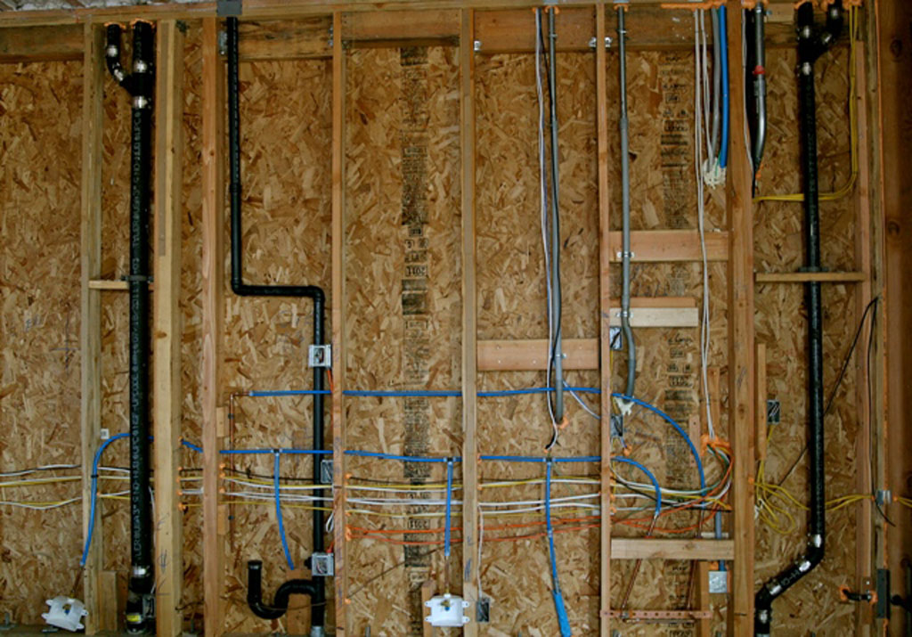
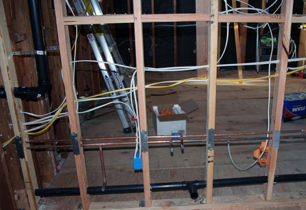
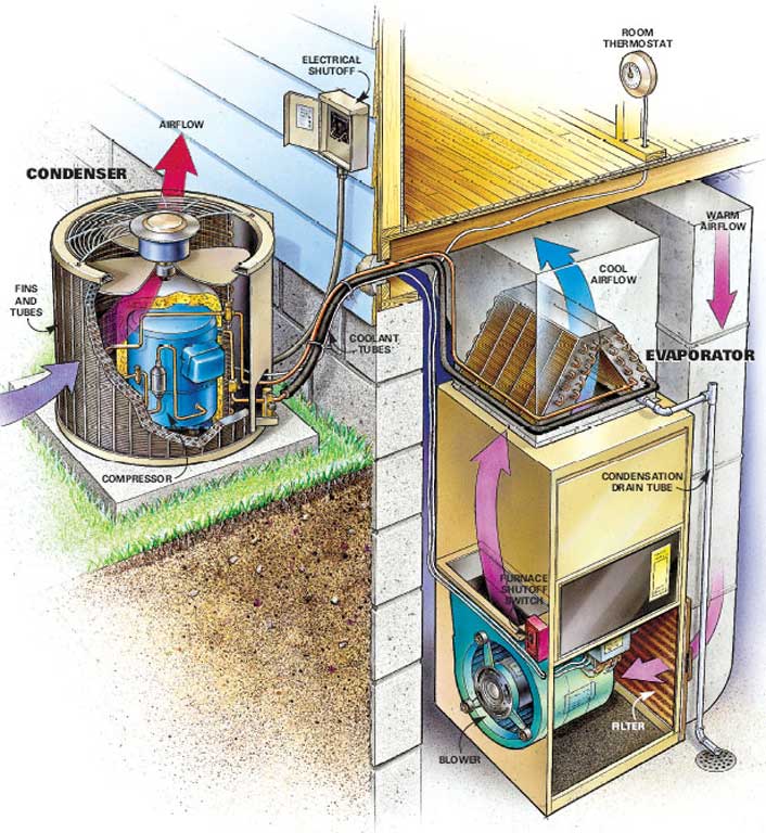
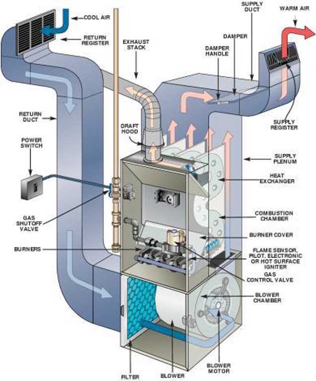
With the rough-in carpenters finishing the frame of the building (platform type, one of several other building types, but the most common), there are several utility resources used in the modern home such as electricity, data, plumbing, heating, ventilation, & air conditioning (HVAC), and gas. As homes have progressed over the last century, they have been made larger, more complex, more utilities, eco friendly, and require more distribution of these utility services/resources. These utilities services/resources are worked on by related trades such as plumbers, electricians, gas fitters, HVAC mechanics, etc., all of which are governed by the the Ontario College of Trades.
Each of these licensed trades needs to properly and safely install these utility systems to control these home resources which make home living comfortable. There are many safety aspects to be aware of such as personal protective equipment, proper construction methods, proper use of tools, following building codes, related trade codes, fire safety, WHIMS, your rights as a worker, and work hazards. Building and trade codes regulate and in some cases standardize materials and installation methods. This activity will focus on some ![]() plumbing and electrical.
plumbing and electrical.
Related General Resource Links for Utility Construction Trades
Here are several links to related utility construction trades, most of which focus also on plumbing and electrical.
What you don't see behind walls.
- Basic PEX connections
- Plumbing Installation
- Rough-in electrical
- Electrical Installation
- Electrical Wiring
- Sheet metal bending
- Furnace add-ons
- Piping and plumbing
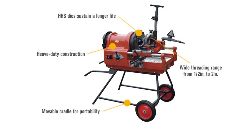
- Plumbing -threads
- Pipe threading
- Residential cabling
- Sample electrical code
- ESA electrical code FAQs
- Visual dictionary - plumbing
- Plumbing basics
 General Plumbing
- Electrical Safety
- Electrical installation
- Electrician's manual
- Residential Wiring
- How to join pex
- PEX manifold
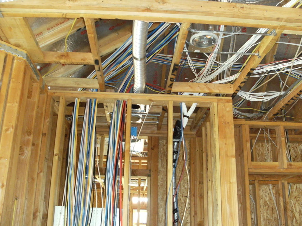
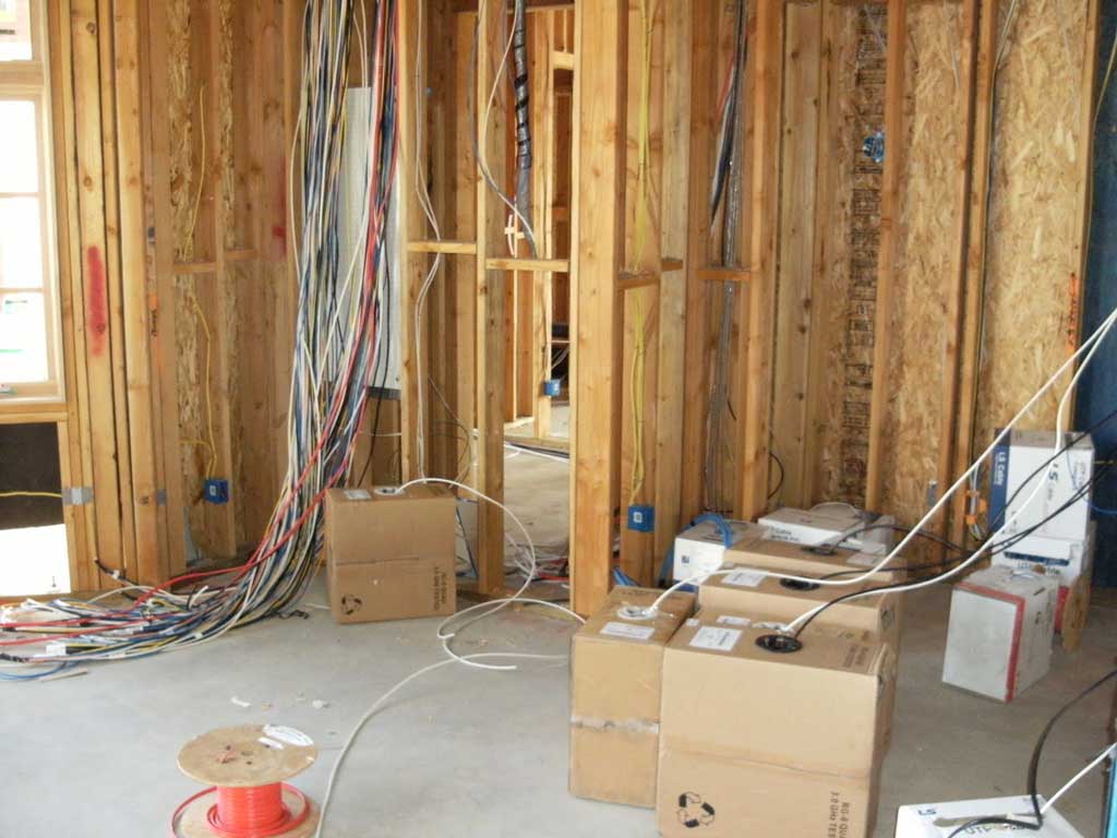
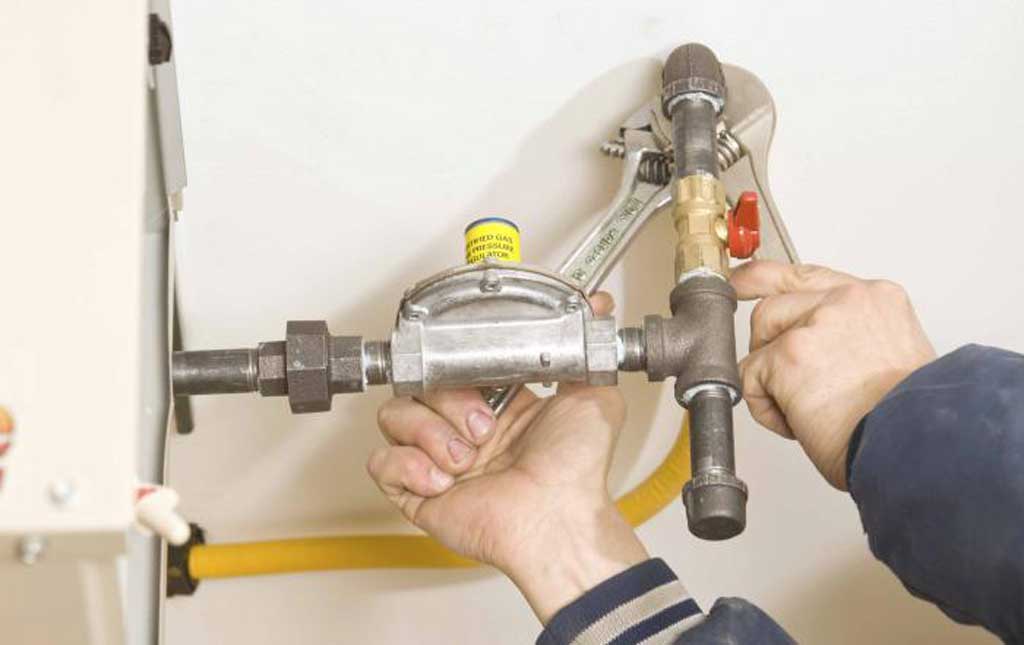
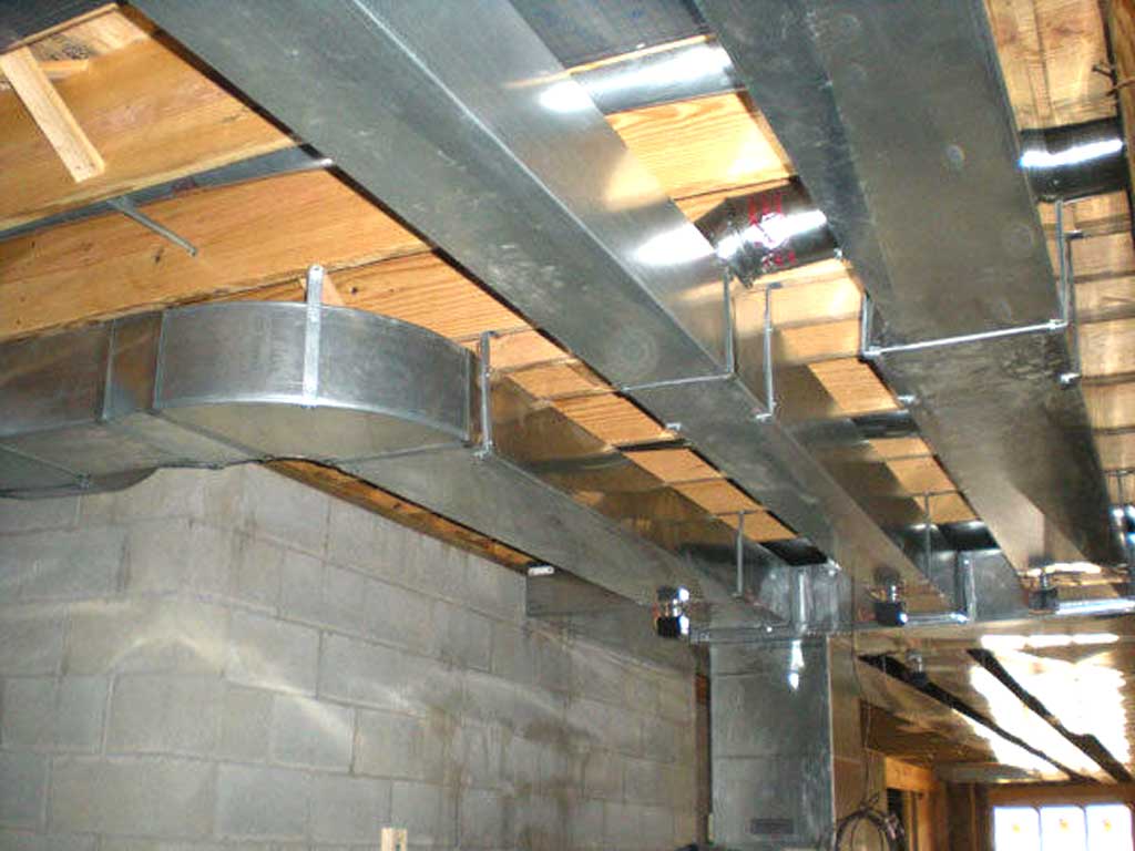
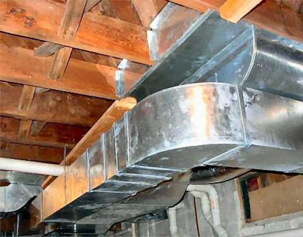
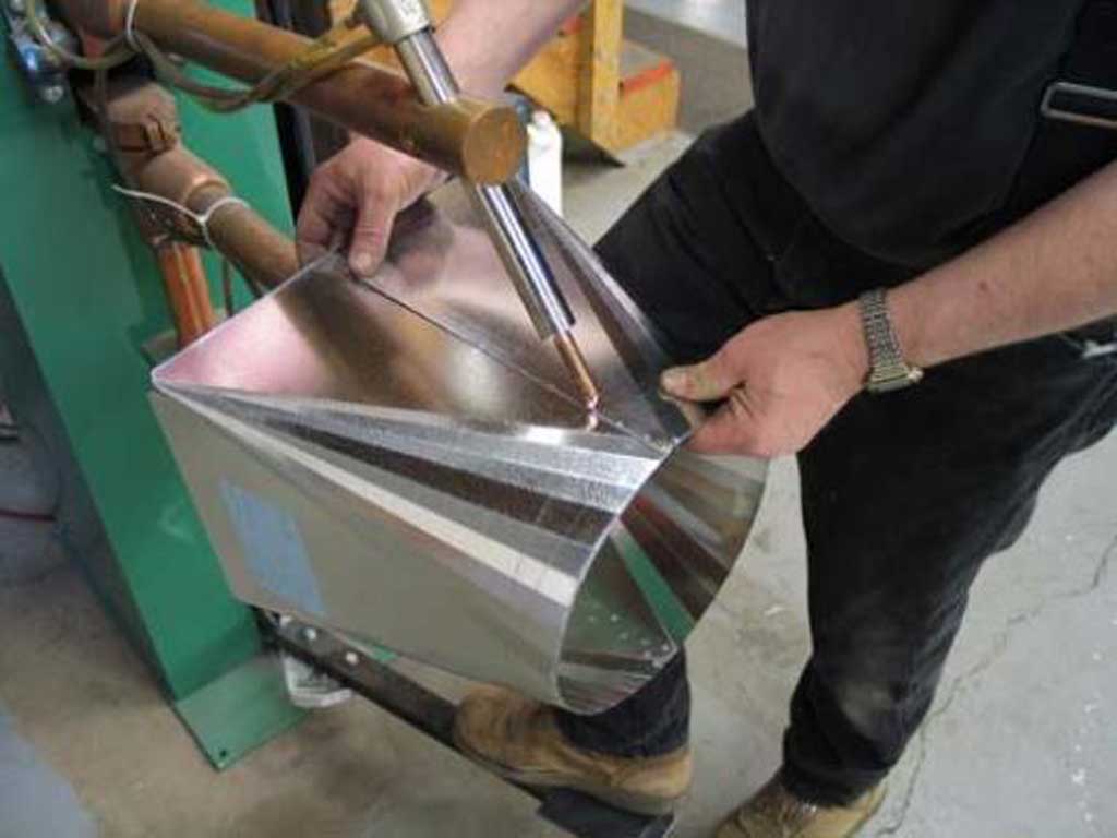
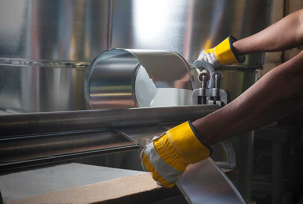
Related Utility Construction Trade Images
The following are some construction utility images related to trades people working in residential homes:
Utility Sample 1
Utility Sample 2
Utility Sample 3
Utility Sample 4

Utility Sample 5
Utility Sample 6

Utility Sample 7
Utility Sample 8
Utility Sample 9
Utility Sample 10
Utility Sample 11

Utility Sample 12
Related Terminology
There are a lot of terms related to the different construction utility related trades in the construction industries. Here are some links to several trade related terms:
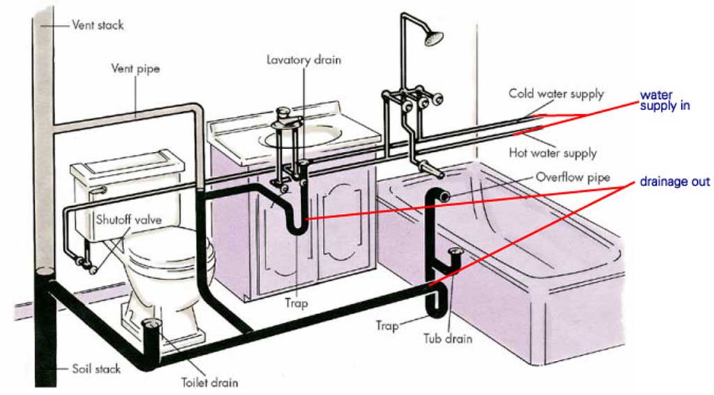
Plumbing
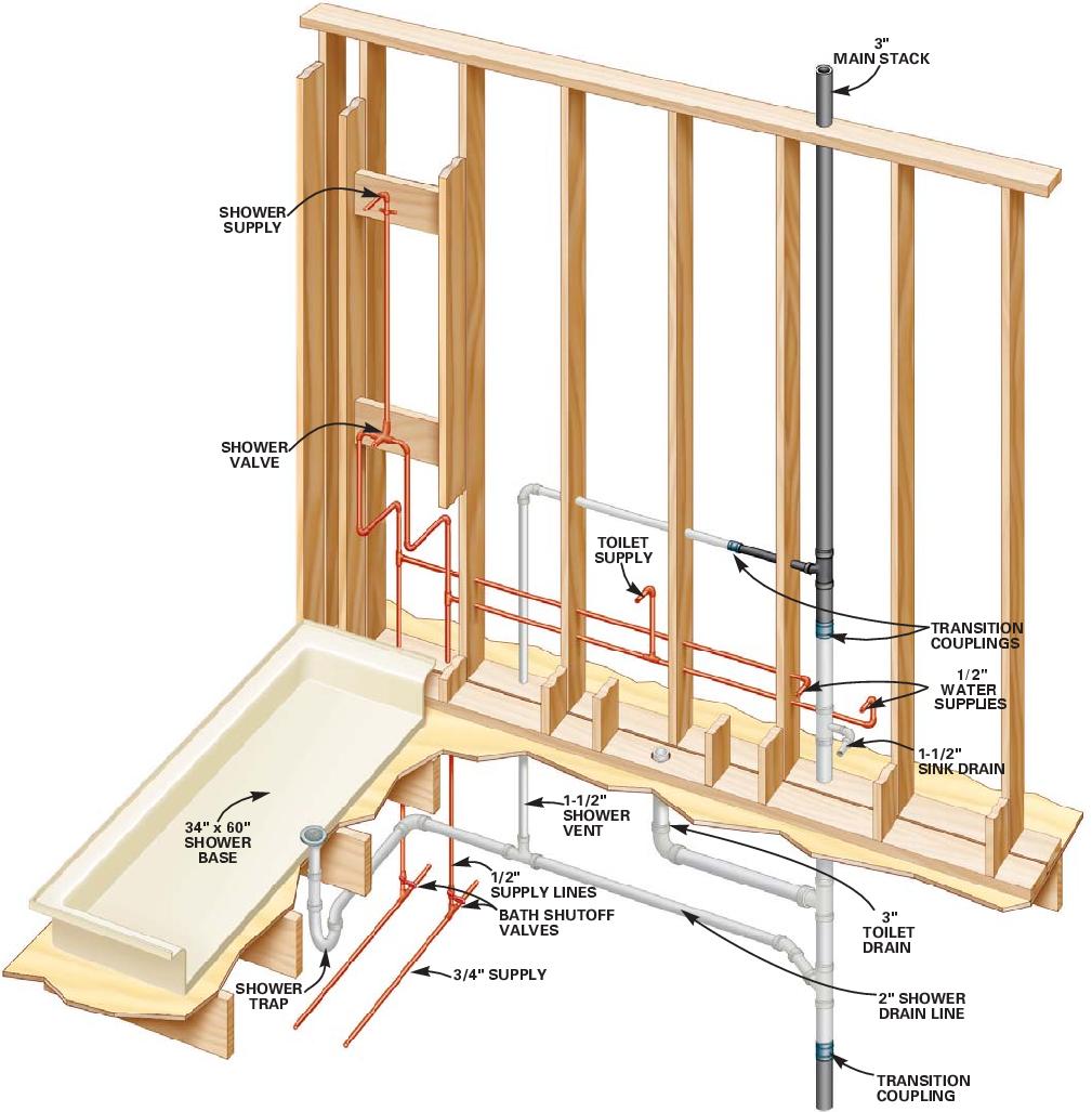
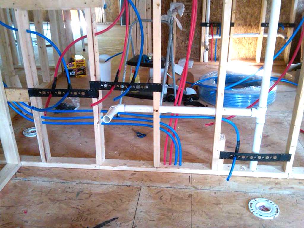
Plumbing systems feature three main components, the water supply (well or municipal supply), the drainage municipal sewer or local septic tank), and the appliance/fixtures (appliance that uses water). History of plumbing, piping was cast-iron drains and brass supply pipes. For the most part, PVC plastic, copper, and flexible cross-linked polyethylene, known as PEX which has increased flexibility and reduced cost, both in labour installation time and cost of materials. Whether the pipes are plastic, metal, or a combination of the two, it's the plumber's skill, design, and installation methods, that will determines how well the system works. Many methods of installation can cause a lot of future problems and just one leaky joint can cause thousands of dollars' worth of damage. Having an undersized or improperly sloped drain will cause clogging while supply pipes that aren't anchored every 6 feet and include pipe system air shock absorbers will cause rattle and thumping every time a faucet is turned off. There's more to proper plumbing than just following the codes and rules, as planning and installing a system that's quiet, efficient, and leak free comes from trade skill, experience and knowledge of these installations. A great plumber will arrange pipes and valves for ease of maintenance, avoid wasting material and/or weakening framing, and wipe joints clean.
For general installation and time lines, sewer stubs are placed before pouring the concrete foundation, but the bulk of the plumbing takes place later. Large plumbing fixtures such as tubs and shower units are often too large to set once walls and doorways are framed in. For this reason they must be installed prior to framing the walls and cover them with cardboard or similar while construction continues to protect their surfaces from scratches and dents. After the rough-in framing is done but before the drywall installation, the ducting, rough-in plumbing, and electrical utilities are installed at the same time. Main drains are installed in floors and connected to the main plumbing stack. Next, rough-in drain fittings are installed for sinks and tubs. Water supply pipes or tubing are installed and toilet flanges are set. Lastly, after finishing the walls, cabinetry, and flooring you can now place and connect sinks, toilets, and other plumbing related fixtures.
Plumbing systems feature three main components, the water supply, the drainage, and the appliance/fixtures. History of plumbing, piping was cast-iron drains and brass supply pipes. For the most part PVC plastic, copper, and flexible cross-linked polyethylene, known as PEX is used with increased flexibility and reduced cost both in labour installation time and cost of materials. Whether the pipes are plastic, metal, or a combination of the two, it's the plumber's skill and installation methods that determines how well the system works. Just one leaky joint can cause thousands of dollars worth of damage.
Plumb. Sample 1
Plumb. Sample 2 ![]() alter.
alter.
Plumb. Sample 3
Plumb. Sample 4 ![]() Dist.
Dist.
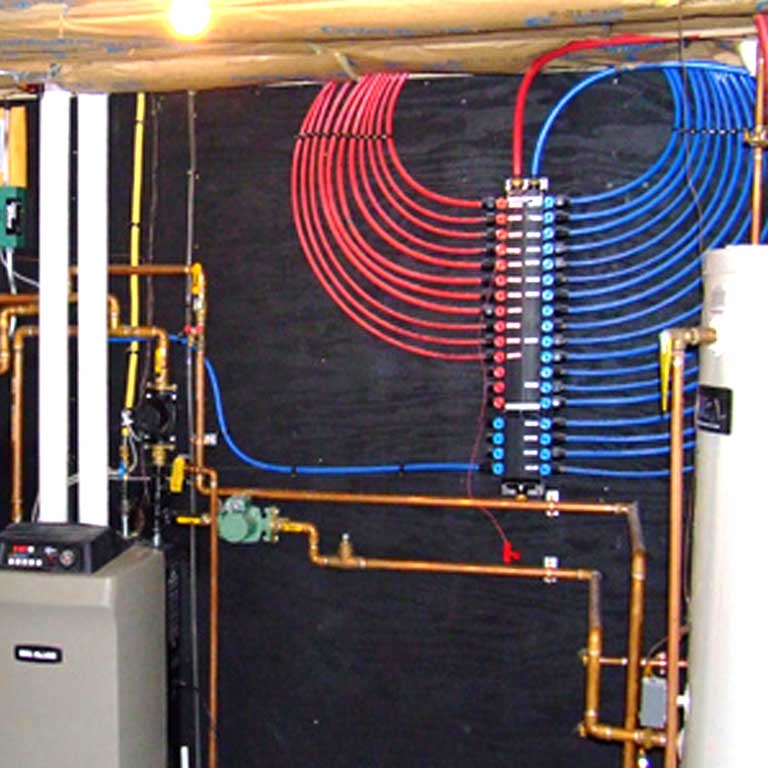
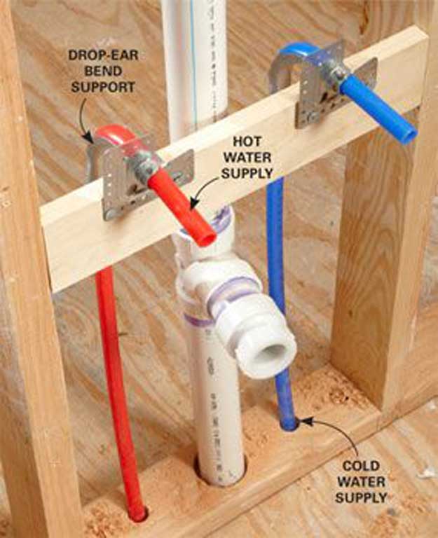
With water supply systems, the main pressurized water supply line enters the house with a pressure of about 50-60 psi (pounds per square inch, which is a measurement of pressure) below frost line, through a water meter, then splits into two lines with one supplying the cold water and the other connecting to the hot water heater. From there, the two lines supply hot and cold water to each fixture and/or appliance. Modern homes have a water ![]() water supply manifold system featuring a large frame - blocked in PEX distribution panel with red (hot water) and blue (cold water) flow valves. Each valve can control individual hot or cold tube distribution or additional manifolds that
water supply manifold system featuring a large frame - blocked in PEX distribution panel with red (hot water) and blue (cold water) flow valves. Each valve can control individual hot or cold tube distribution or additional manifolds that ![]() supplies water to a fixture. Using a manifold system like this makes it simple to control the flow and/or shut off the water supply to one fixture without shutting off water supply to the whole house giving the homeowner flexibility.
supplies water to a fixture. Using a manifold system like this makes it simple to control the flow and/or shut off the water supply to one fixture without shutting off water supply to the whole house giving the homeowner flexibility.
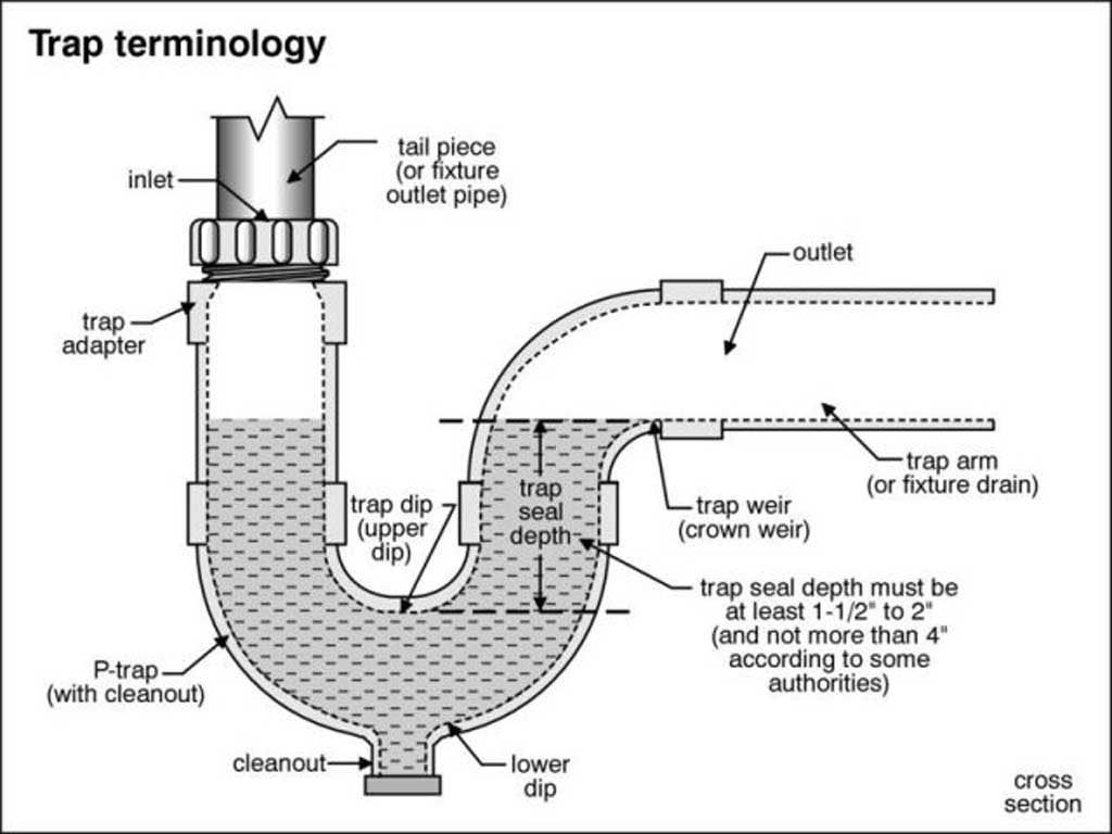
![]() Drainage is another important part of the plumbing. A main stack connects all drainage and venting to roof. The main soil or waste stack, usually 4" size in diameter, is gravity fed from all drains in the home, and runs vertically from beneath the ground floor to above the roof line. The waste drains connect to the stack, directing waste downward to the main sewer drain, which then exits the home below frost line and ties into the municipal sewer system or runs to a personal septic system. Plumbing fixtures usually will have both a drain trap and vent. The drain trap is a u-shaped pipe that connects to the bottom of a sink, shower, or tub which retains a small amount of water that prevents the smelly sewer gases from backing up into the house. All plumbing fixtures require drain traps except the toilets, which comes with an internal trap built into their base. Vents allow the pressure to equalize on both sides of a trap, allowing the trap to hold the water effectively and avoid "trap suck-out" which otherwise might occur if not in place. For these drains to work optimal, a constant source of air through vents will prevent water locks causing clogs. All drains require ventilation, but a single vent, usually installed behind a sink, can serve additional fixtures and appliances that connect within 10 feet of a common drain line. Vent pipes, are generally 1.5 to 2 inches in diameter and connect to the stack in the attic. When a fixture sits too far from a common vent, it requires an additional vent piping, to connect to the stack or may exit the roof separately, depending on the home's layout.
;
Drainage is another important part of the plumbing. A main stack connects all drainage and venting to roof. The main soil or waste stack, usually 4" size in diameter, is gravity fed from all drains in the home, and runs vertically from beneath the ground floor to above the roof line. The waste drains connect to the stack, directing waste downward to the main sewer drain, which then exits the home below frost line and ties into the municipal sewer system or runs to a personal septic system. Plumbing fixtures usually will have both a drain trap and vent. The drain trap is a u-shaped pipe that connects to the bottom of a sink, shower, or tub which retains a small amount of water that prevents the smelly sewer gases from backing up into the house. All plumbing fixtures require drain traps except the toilets, which comes with an internal trap built into their base. Vents allow the pressure to equalize on both sides of a trap, allowing the trap to hold the water effectively and avoid "trap suck-out" which otherwise might occur if not in place. For these drains to work optimal, a constant source of air through vents will prevent water locks causing clogs. All drains require ventilation, but a single vent, usually installed behind a sink, can serve additional fixtures and appliances that connect within 10 feet of a common drain line. Vent pipes, are generally 1.5 to 2 inches in diameter and connect to the stack in the attic. When a fixture sits too far from a common vent, it requires an additional vent piping, to connect to the stack or may exit the roof separately, depending on the home's layout.
;
Electrical
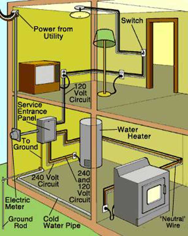
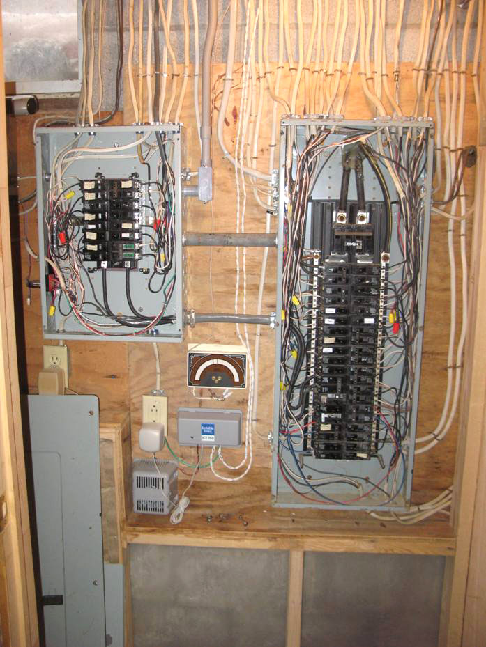
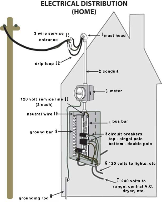
Generally electrical supply is brought into a home by either a underground or above ground wiring, through a meter, then to a ![]() service panel. From the service distribution panel, individual circuits are used to distribute power through-out the home based on their amperage and type of
service panel. From the service distribution panel, individual circuits are used to distribute power through-out the home based on their amperage and type of 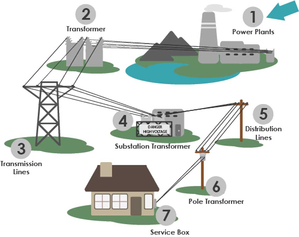 power needed. For example a stove on it's own is on a 40 amp breaker and this breaker is designed to protect the wire from overload draw from the stove. Code regulations dictate the safe amperage that the # 8 AWG (American Wire Gauge -a standard wire sizing used).
A little history of wire started with bare wire, sometimes covered with cloth, were stapled to wood framing, spliced and soldered for connections. Around the 1880-1930's, ![]() knob and tube with ceramic tubes going through construction members, and ceramic stand-off knobs to space away individual wires from construction framing. Another method later, was the use of metal sheathing made with paper insulators and lead sheathed exterior. Eventually rubber insulated cables in the 1920's started to be used and by the 1950's PVC (Polyvinyl chloride) became more common and is widely used today. Around 1960 to the mid 70's industry started using aluminum because of the steep rise in copper cost, but have since gone back to copper because of several problems such as wire oxidization, a relatively higher coefficient expansion rate and creek, and galvanic corrosion (what happens when two dissimilar metals are touching with the presents of electrolyte). Aluminum is still used in utility transmission/distribution and some airplanes today because of its weight advantage.
knob and tube with ceramic tubes going through construction members, and ceramic stand-off knobs to space away individual wires from construction framing. Another method later, was the use of metal sheathing made with paper insulators and lead sheathed exterior. Eventually rubber insulated cables in the 1920's started to be used and by the 1950's PVC (Polyvinyl chloride) became more common and is widely used today. Around 1960 to the mid 70's industry started using aluminum because of the steep rise in copper cost, but have since gone back to copper because of several problems such as wire oxidization, a relatively higher coefficient expansion rate and creek, and galvanic corrosion (what happens when two dissimilar metals are touching with the presents of electrolyte). Aluminum is still used in utility transmission/distribution and some airplanes today because of its weight advantage.
Elect. Sample 1
Elect. Sample 2
Elect. Sample 3
Elect. Sample 4
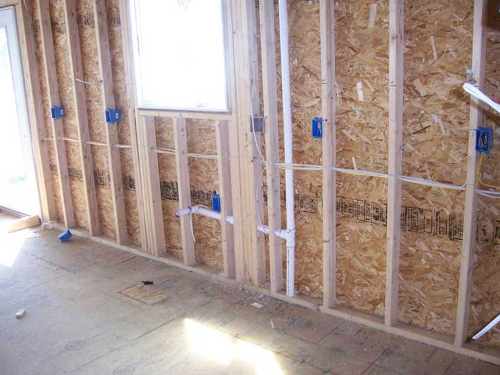
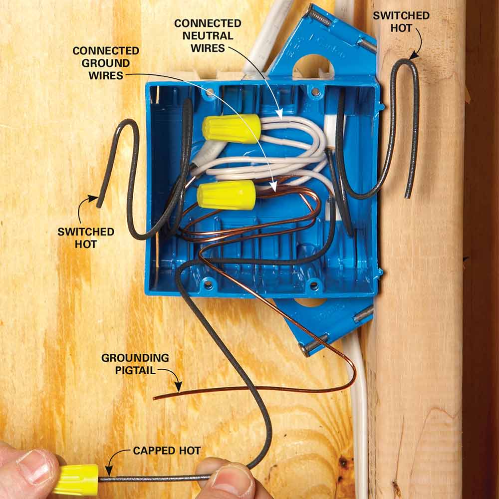
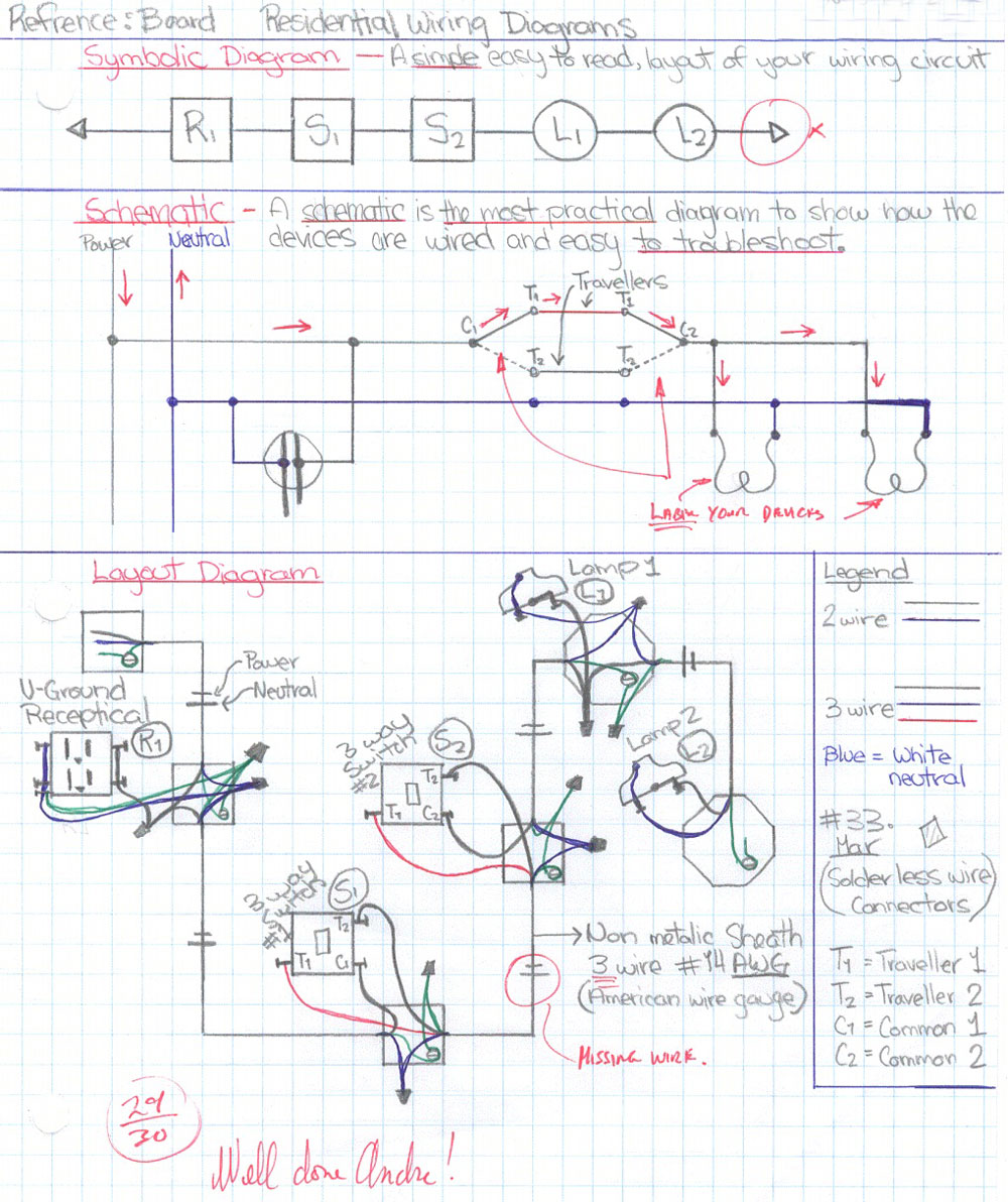
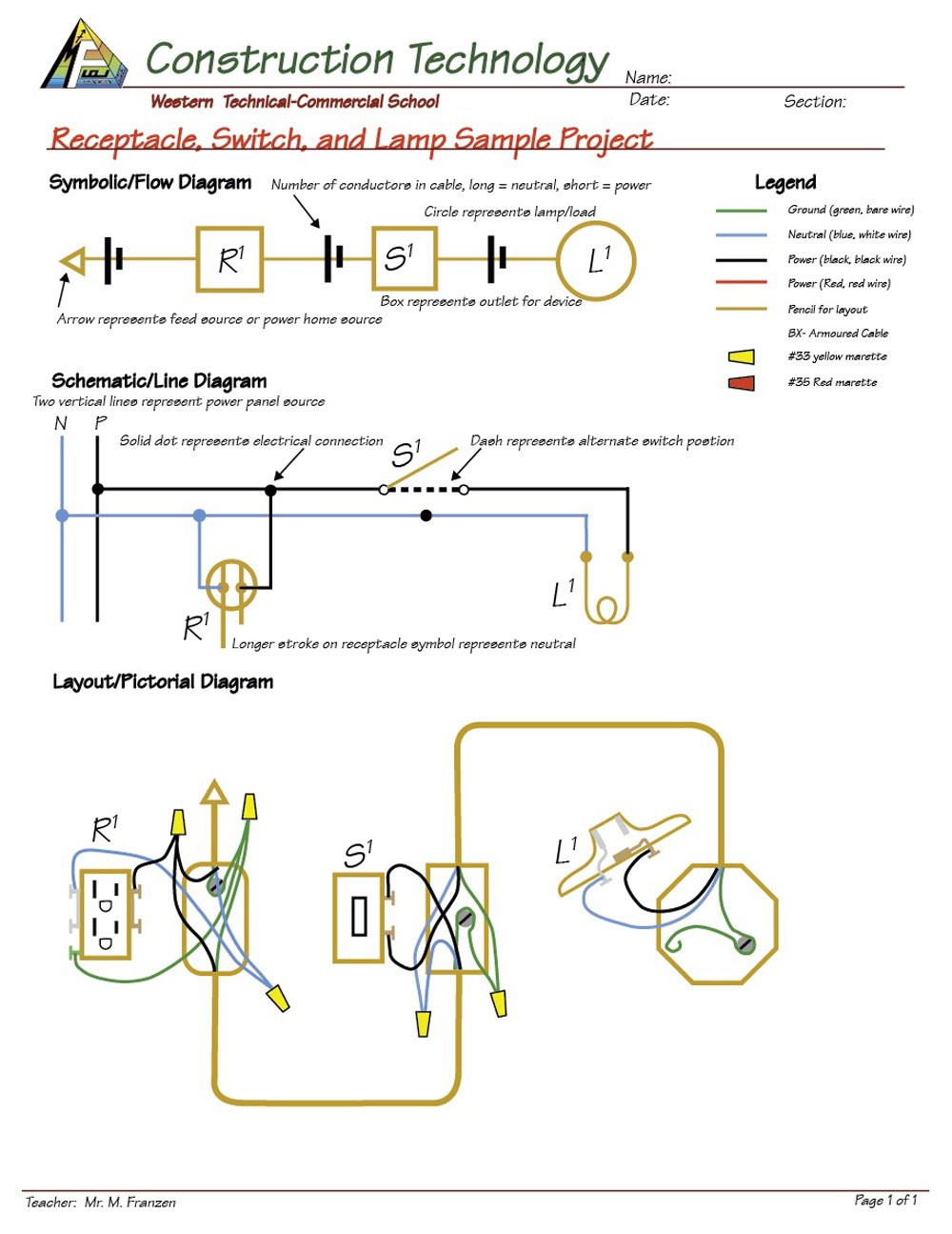
The Canadian Electrical Code dictates standards and safety regulations so that electrical wiring and devices are safely installed for use by the homeowner. Electricians use wiring diagrams in the form of symbolic (flow with simple shapes related to location and devices), schematic (ladder diagram of wire connections), and layout (pictorial of devices, boxes, locations, and connections) to follow and wire up devices. After familiarizing and understanding the details with wiring and device connections, wiring circuit connections can be visualized and wire up circuits using just the wiring plans. Device boxes used to connect typical home electrical appliances come in many sizes and shapes with the three most common being the rectangular (for receptacles and switches), square (for junctions), and octagonal (for lamps). There are many rules and regulations, constantly being updated, to keep in mind when installing these devices. Generally boxes are mounted with the thickness of the finished wall, typically drywall, so that they are flush with finished edge (hydro code regulations), then electrical device is screwed to the box along with a device cover.
Three typical devices used are the receptacle, switch, and lamp holder. A typical duplex u-ground 120 volt (voltage amount of pressure of electricity) receptacle outlet and similar devices are connected by a #14 AWG Romex cable to the box and fed from the service distribution panel. Wire preparation must be carefully done to ensure excellent wire connections which commonly include; appropriate conductor length inside box, no nicks with wire stripped, tight marret connections, ![]() appropriate box fill, and excellent wire terminations on terminals of electrical devices for safe home use. Improper wiring methods can easily cause fires and cost a homeowner their home if not wired properly
appropriate box fill, and excellent wire terminations on terminals of electrical devices for safe home use. Improper wiring methods can easily cause fires and cost a homeowner their home if not wired properly
Create/Construct:

Complete the ![]() Construction Utilities Handout to explore and familiarize yourself with the basic and common utilities found in the home. For the practical part of this project you will follow the steps below to add the plumbing and electrical components to your project. The plumbing should be pretty straight forward and drain will be "dry fitted" rather than glued. The electrical you have already had some experience with, and as such should be able to show your knowledge, skills, and experience with excellent technique and quality install with the finished work. Each group will receive the appropriate materials to complete the work. Measure carefully as to not waste material. Click here to download print PDF version of steps below.
Construction Utilities Handout to explore and familiarize yourself with the basic and common utilities found in the home. For the practical part of this project you will follow the steps below to add the plumbing and electrical components to your project. The plumbing should be pretty straight forward and drain will be "dry fitted" rather than glued. The electrical you have already had some experience with, and as such should be able to show your knowledge, skills, and experience with excellent technique and quality install with the finished work. Each group will receive the appropriate materials to complete the work. Measure carefully as to not waste material. Click here to download print PDF version of steps below.
Plumbing Steps
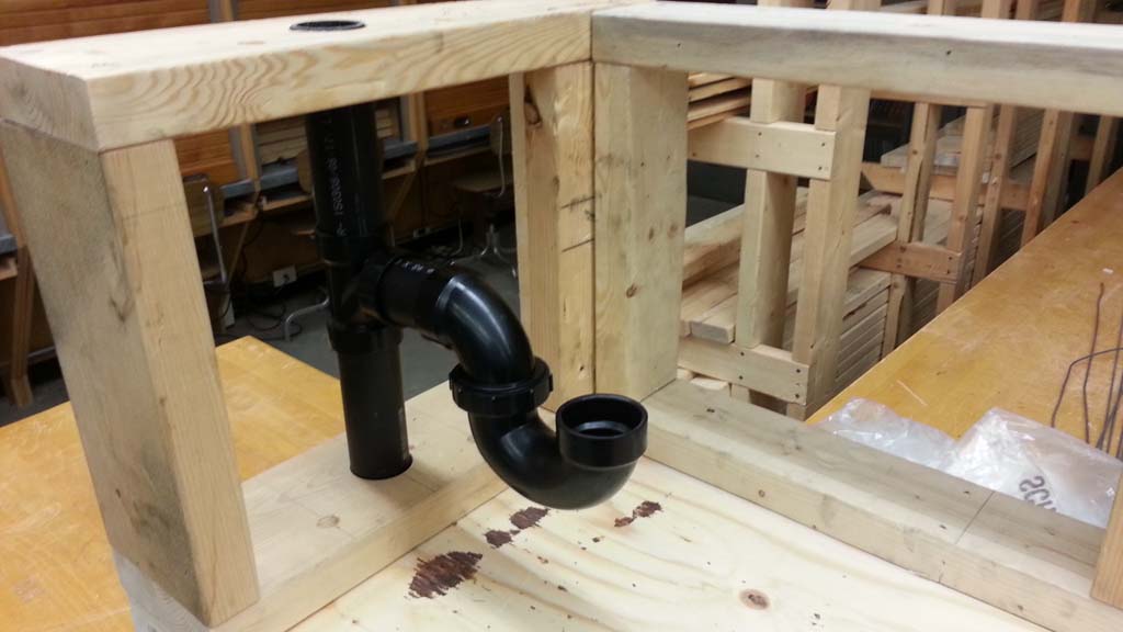
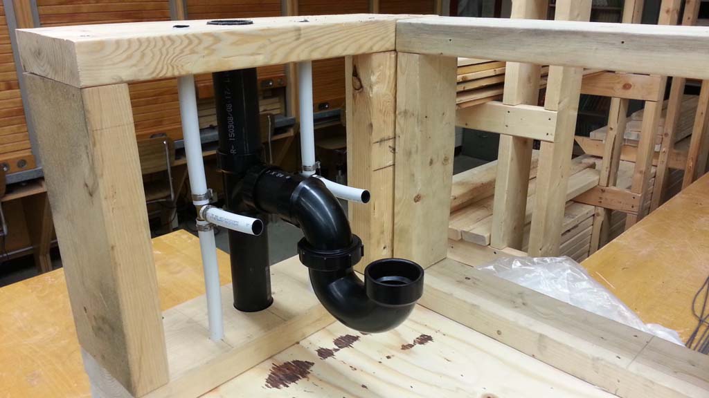
- Bottom ABS drain pipe - On the exterior wall, you should have a 12" spacing height-wise between the bottom plate and top plate. Taking into account the 3/4" depth 1 7/8" hole you previously bored out, you are to dry fit a 1 1/2" ABS diameter pipe up to a T fitting to be located exactly in the centre, OC of the top and bottom plates. Careful calculation and measurement is required to cut the 1 1/2" ABS pipe to the correct length using either a hack saw or chop saw.
- Top ABS drain pipe - Measure and cut, and install another piece of ABS drain pipe do that it ends flush with the top of your top plate.
- P-Trap - you will need to make a ABS nipple (short piece, showing 1 1/2" pipe between fittings) to connect the T fitting to the P-trap the
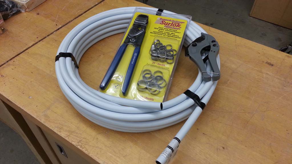
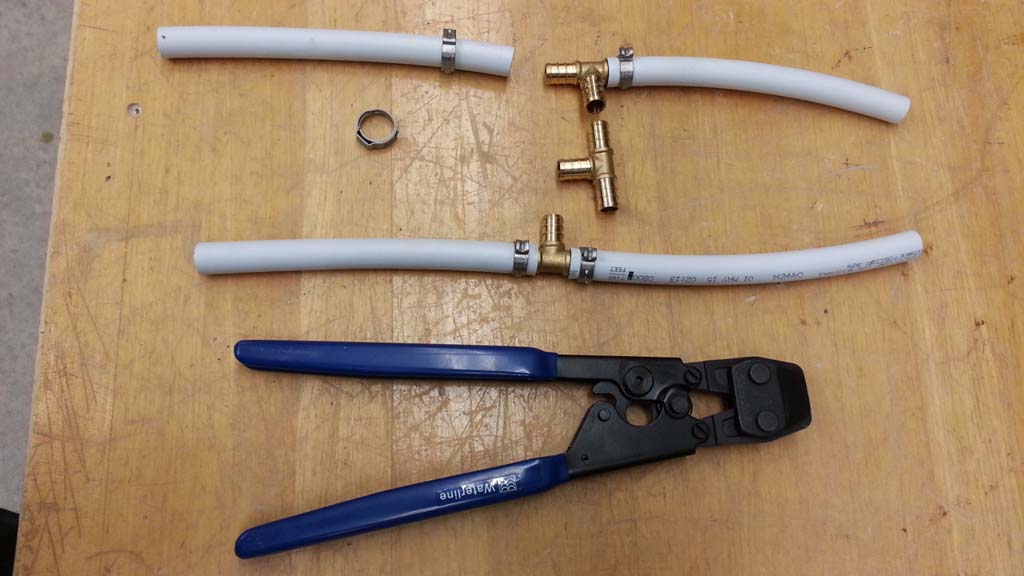
- Bottom Pex water tubing - the hot and cold 1/2" water tubing will also be measured so that the T is exactly centre OC between the top and bottom plates. You must take in account the 3/4" depth the tubing will sit into the bottom plate plus half the height of the space between the top and bottom plate minus the brass T fitting and taking in account T fitting tube over-lap to have the T fitting exactly centre, OC of top and bottom plates
- Top Pex water tubing - measure and cut so that the Pex tubing length from the T to flush of the top plate taking into account the T fitting tube overlap connection.
- T-tap tubing extension - cut two 3" pieces to represent going to the hot and cold valves which in turn go to the water faucet.
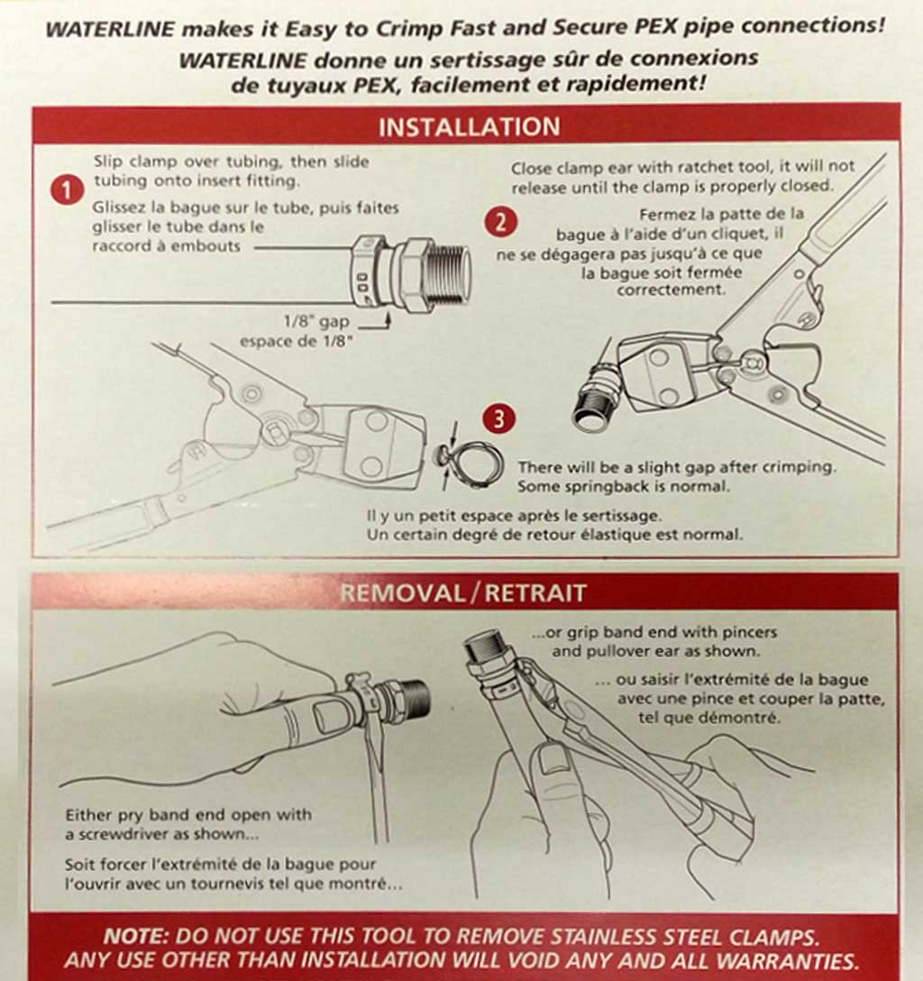
- Crimping Pex - Once you have all your tubing cut, double check and do a dry fit to ensure accuracy, then using the crimper and the 1/2" tubing crimps, crimp the T fitting into place on both the hot and cold water supplies and slide into place
Utility Sample 1
Utility Sample 2
Utility Sample 3
Utility Sample 4
Utility Sample 5
Utility Sample 6
Utility Sample 7
Utility Sample 8
Electrical Steps
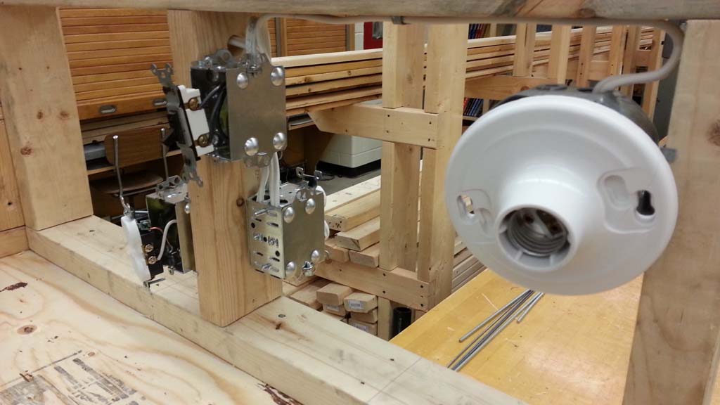
- Wiring diagram - Using a blank wiring template, individually draw out your electrical symbolic, schematic, and layout diagrams using pencil and after using legend with colour for the power (black), neutral (blue), and ground (green) similar to sample, to show how wires are connected and hand-in for evaluation
- Box rough-in - Start by measuring and marking locations for each of your boxes. As this is a partial sample, receptacles will be mounted 4.5" OC above finished floor, with finished hard wood floor to be 1/2" above plywood sub-floor. Switch and octagon box to be mounted 9.5" OC from finished floor.
- Cable holes - Using a 3/4" speed (spade) drill bit carefully align and drill holes, one from basement through bottom plate, and the second hole on the first stud supporting both receptacle and switch boxes near the top plate
- Cable rough-in - route and run your cables between each of the boxes with the feed supply coming from the basement as shown in sample 7, then to the first receptacle, then to the second receptacle, to the switch, then to the octagon box. Remember to have 6-7" of wires inside each box from cable terminations, allowing for feed cable ground wire to go under ground screw first and still have at least 5" left to spare for connections. Ensure you have cable stapled properly according to the hydro code.
- Rough-in inspection - have instructor inspect your work to ensure box locations, cables, clamps, wire lengths, grounding, cable supports are all done correctly.
- Receptacle connections - normally devices are connected after the drywall has gone up, but at this stage we will connect devices to bring closure to the electrical project section, so you will connect up both receptacles using marrets and one terminal for each as previously learned in past project.
- Switch and lamp connections - connect up a single pole, single throw toggle switch with the feed going to top of switch terminal and load going to lamp and return wires marreted together, then connect up the lamp with extra ground wire safely tucked to back of box
- Testing cct - Using a multi-meter, check that all of your circuit is properly connected and working. be prepared to demonstrate your it's working condition and has no shorts.
Student sample
Class sample ![]() PDF
PDF
Blank template ![]() PDF
PDF
Evaluation:
When installing the sample utilities in your groups of three, you will be marked on your knowledge, steps taken, participation, effort, teamwork, progress, and process. Using the weekly ![]() task report will allow you individually to track and record your individual progress daily, get initialed by instructor, and earn individual marks upon submission at the end of each week. Below is a breakdown of the project sections and what will be evaluated:
task report will allow you individually to track and record your individual progress daily, get initialed by instructor, and earn individual marks upon submission at the end of each week. Below is a breakdown of the project sections and what will be evaluated:
| Evaluation Breakdown Component Descriptions | Marks |
|---|---|
| Always double check that you have completed all components for full marks. | |
| Utilities Handout - |
50 |
| Wiring Cct Diagrams - |
30 |
| Group Utilities Installed - locations, measurements, cuts, connections, and group work | 60 |
| Individual Task Reports - |
~ |