Unit 3: Wire Joints, Devices, and Wiring
This unit focuses on hands-on trade projects. With the shop well suited to work with electrical construction, looking closer at electrical related projects will give students some insight into this field.
Course Units and Descriptions
Use this table for an overview and navigate to each of the course unit pages.
| Unit | Description |
|---|---|
| Review course outline for more details | |
| 1 | Safety, Shop, and Practice - intro, safety, tools , machines, projects, and reporting |
| 2 | Technical Drawings and Circuit Theory - reading drawings, code, and wiring ccts |
| 3 | Wire Joints, Devices, and Wiring - wire, joints, elect. devices, and wiring methods |
| 4 | Building Foundation to Finish - concrete base, carpentry, electrical, plumbing, and drywall |

Unit Content Activity Quick Links, Click to Jump to Specific Activity!
 Unit 3, Act. 1: Triangle Wiring Challenge
Situation:
As with any trade, basic hands-on-skills are important. As we are going to be wiring up circuit devices, it is important to know how to work with wire and their related tools.
Problem/Challenge:
Create a 6" wire triangle made up of
- 5 #14 AWG solid red wire
- 5 #12 AWG solid black wire
- 3 #12 AWG stranded white wire
with two western union joints, two T-taps, and 4 rat tail joints. The western union, T-tap, and two stranded ends are to soldered, with heat shrink and electrical tape used as insulation for those joints.
Investigation/Ideas:
Here are two handouts that you can download that supplement this project to help with creating the wire triangle:
The following background link resources will help with your wire joint project:
 Wiring Techniques
 How to Heat Shrink Soldered Wire Joints
- Heat-shrink tubing
- How to Heat Shrink Wire
- What is Electrical Tape?
- Electrical tape
- 6 Tips for Using Electrical Tape
Create/Construct:
There are three major sections of this project, namely wire stripping, wire joints, and soldering.
Wire Stripping & Joints
Follow these steps
- Strip 5 7" black #12 AWG wires with the wire stripper and half with the knife
- Strip 5 7" red #14 AWG wires with the wire stripper and half with the knife
- Strip 3 7" white #12 AWG wires with the wire stripper and half with the knife
- Have all your work peer evaluated, then bring it to the instructor for evaluation
Step 1
Strip wires
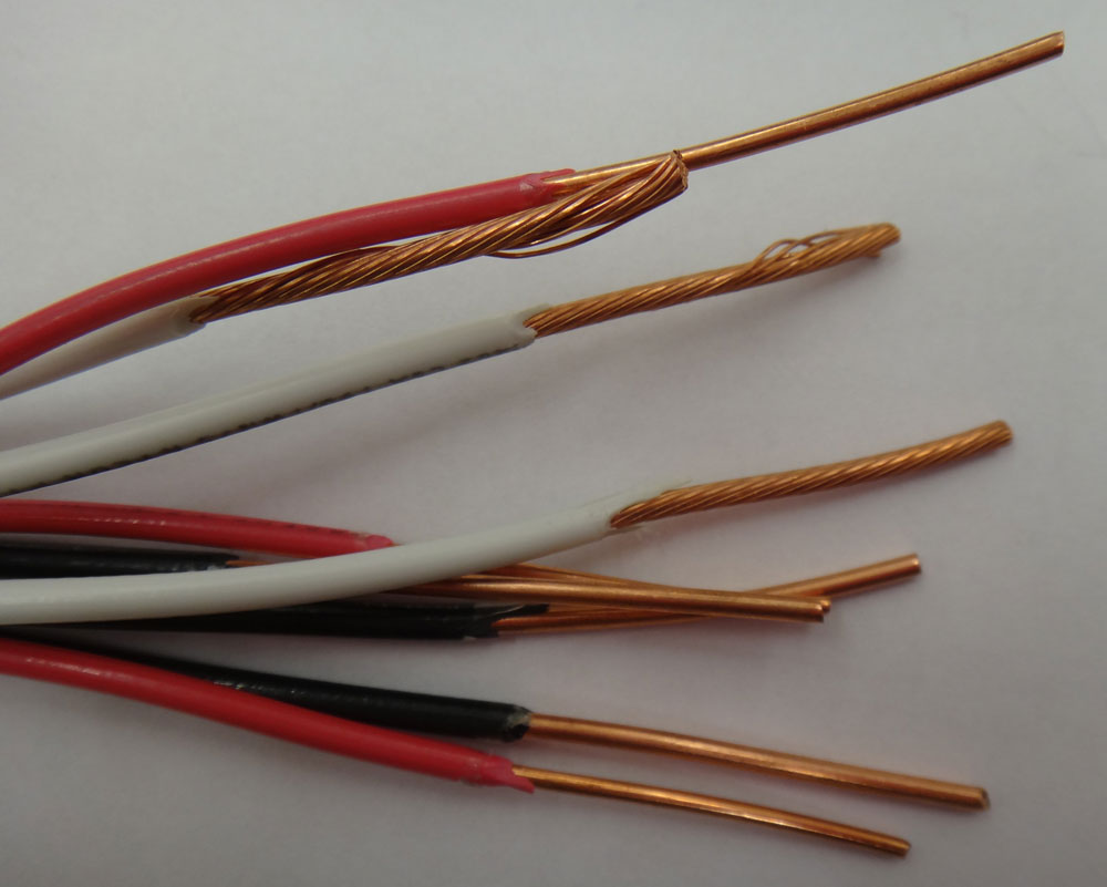
Step 2
Knife Stripping
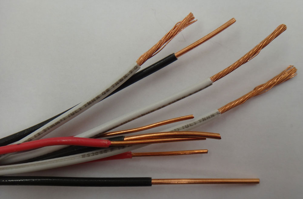
Step 3
Plier Wire Stripping
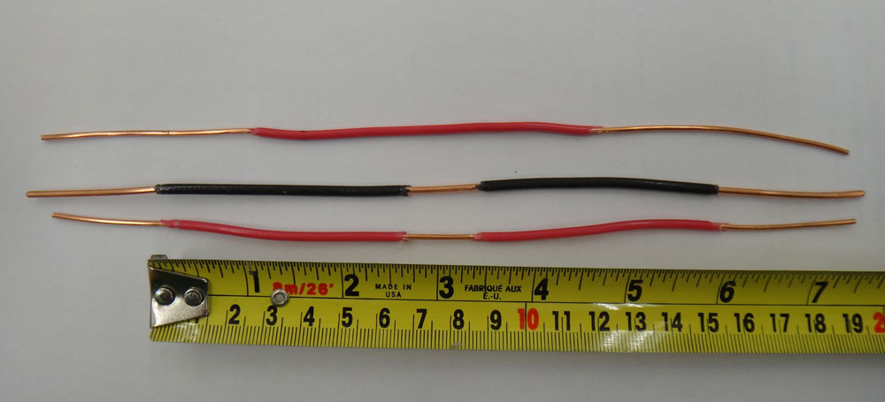
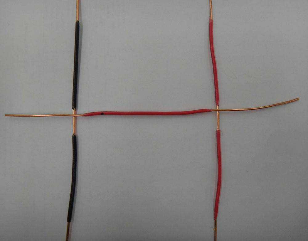
Step4
Build 2 Western Unions
Below shows steps to making two t-taps back to back. Watch your measurements. should be going for some accuracy so that wire triangle will look good.
Step 5
Strip wires
Step 6
Knife Stripping
Step 7
Plier Wire Stripper

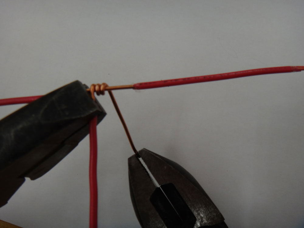
Step 8
Western-T-taps
Soldering
Review the Soldering Method ![]() hand-out. You will find the information you need and steps to solder properly. Below you will find some images showing critical shots during the soldering process through tinning and joint soldering. It is important to wear safety glasses while soldering and ensure that you use flux resin on all of your solder joints prior to applying heat.
hand-out. You will find the information you need and steps to solder properly. Below you will find some images showing critical shots during the soldering process through tinning and joint soldering. It is important to wear safety glasses while soldering and ensure that you use flux resin on all of your solder joints prior to applying heat.
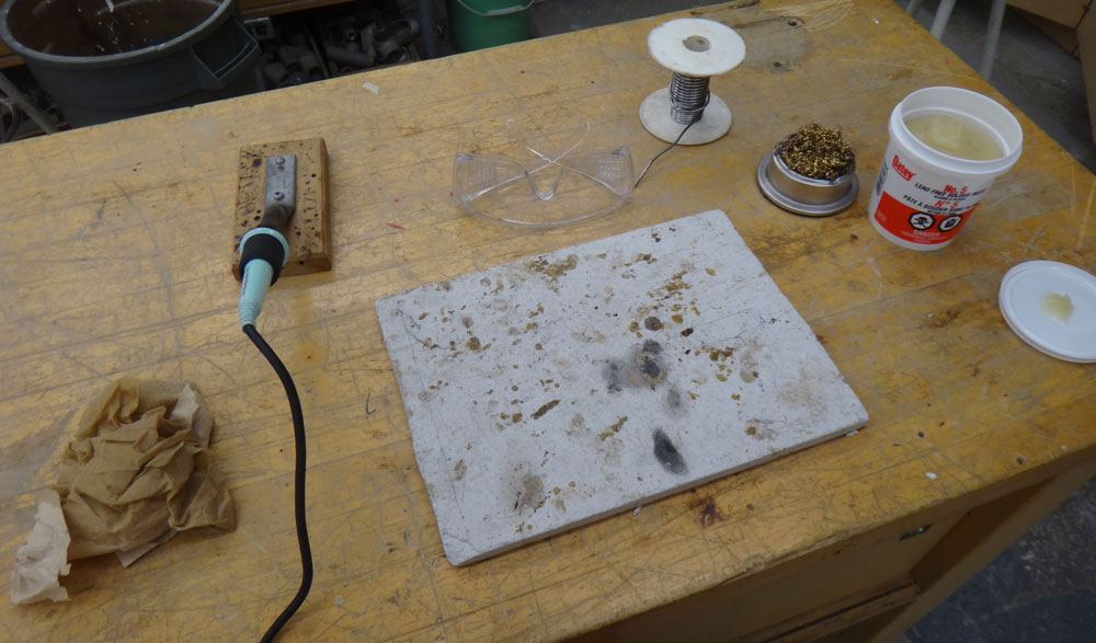
Step 1
Solder station set-up
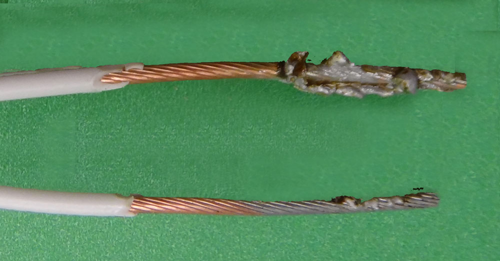
Sample
Bad & Good tinning
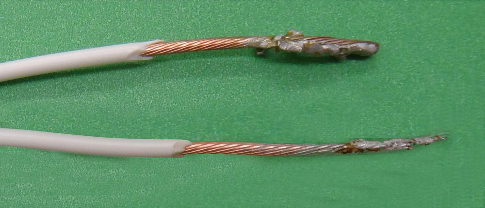
Sample
Bad and Good- other side
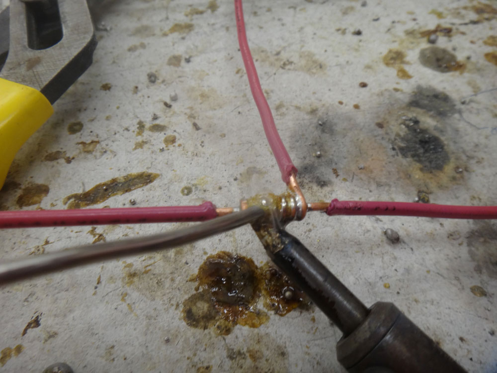
Below shows the critical soldering characteristics while soldering a wire joint.

Step 1
Heat Joint - Solder Bridge
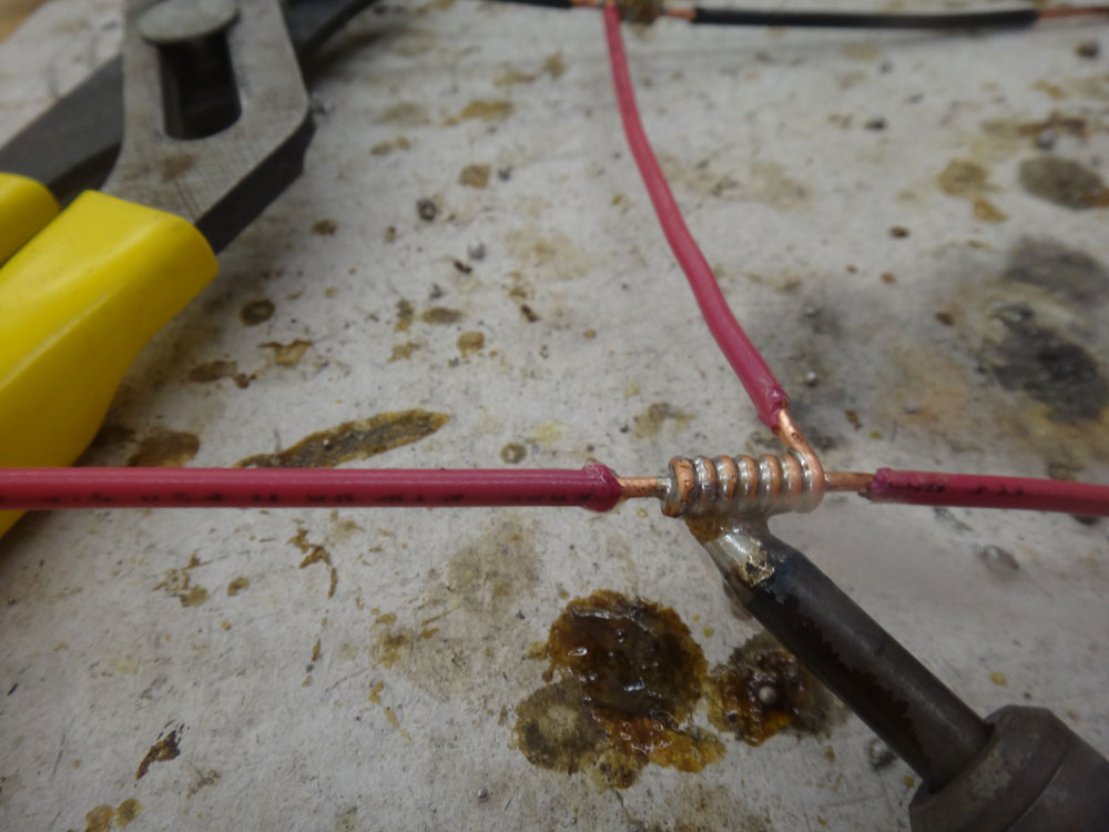
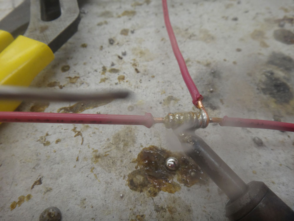
Step 2
Joint Sucking Up Solder
Step 3
Applying Solder Above
Step 4
Finished
These images below showing finished sample joints.

Finished T-Tap
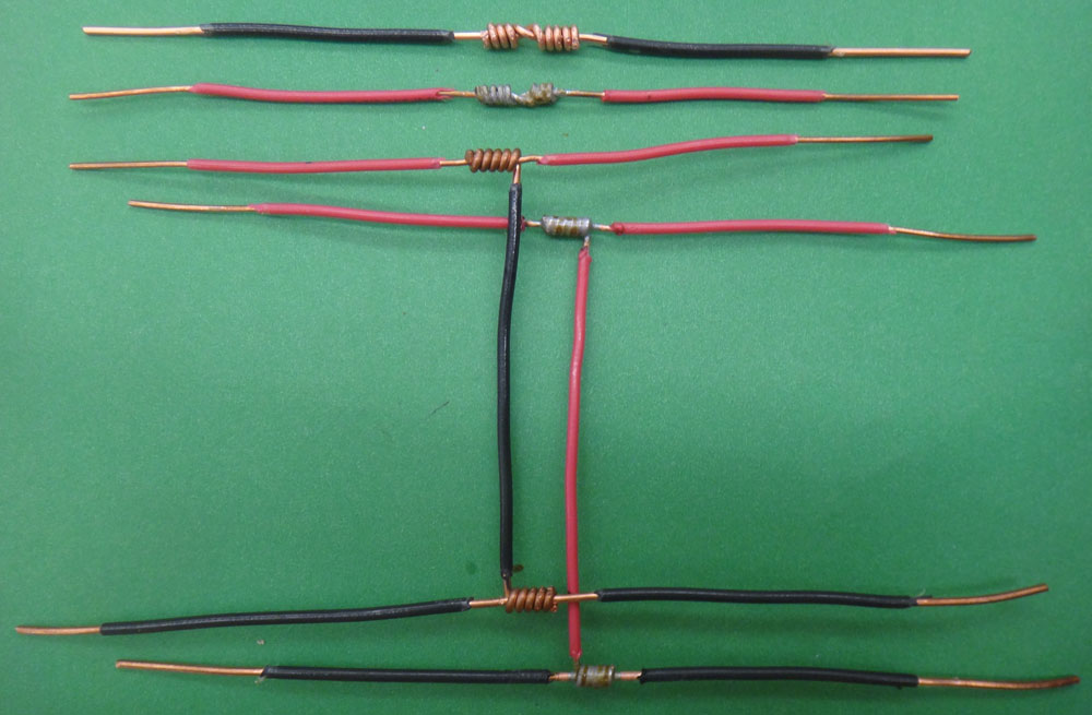
All Wire Joints
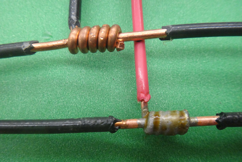
T-Taps

Western & T-Taps
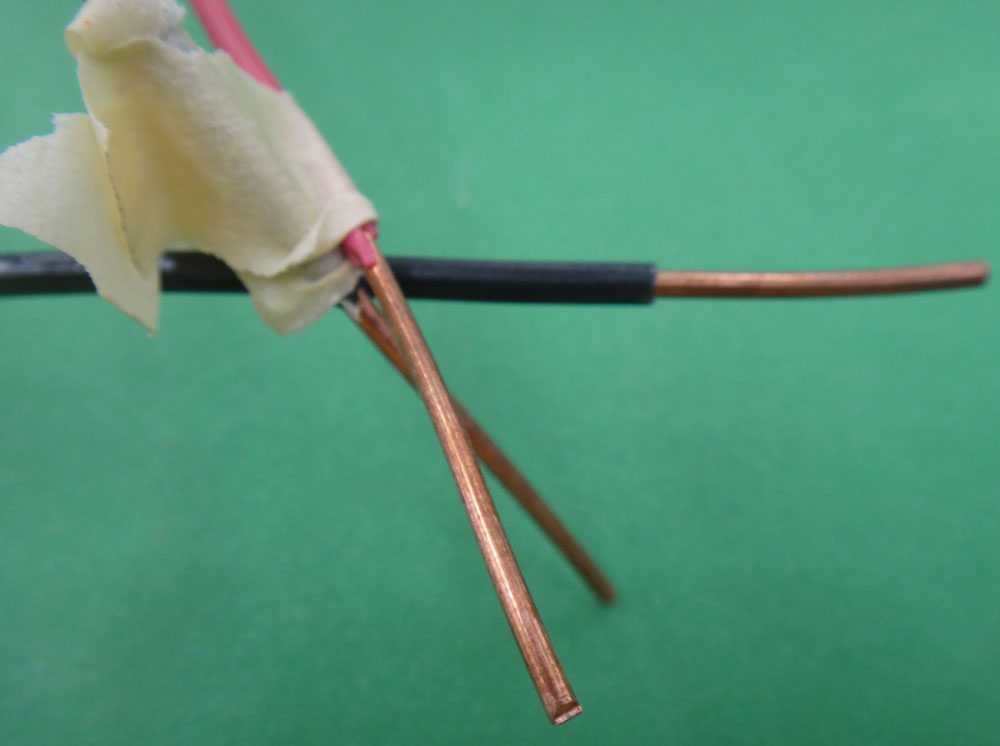
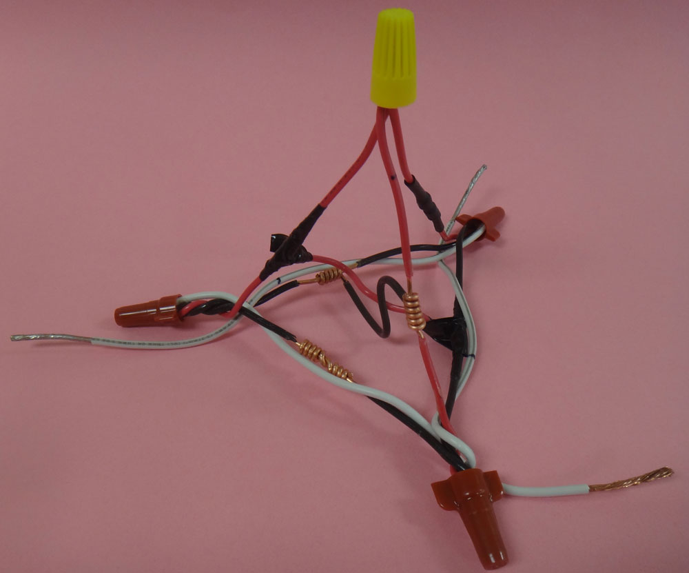
Finished Pyramid and Rat Tails
Here are some pictures of the finished Pyramid project with some close-ups.
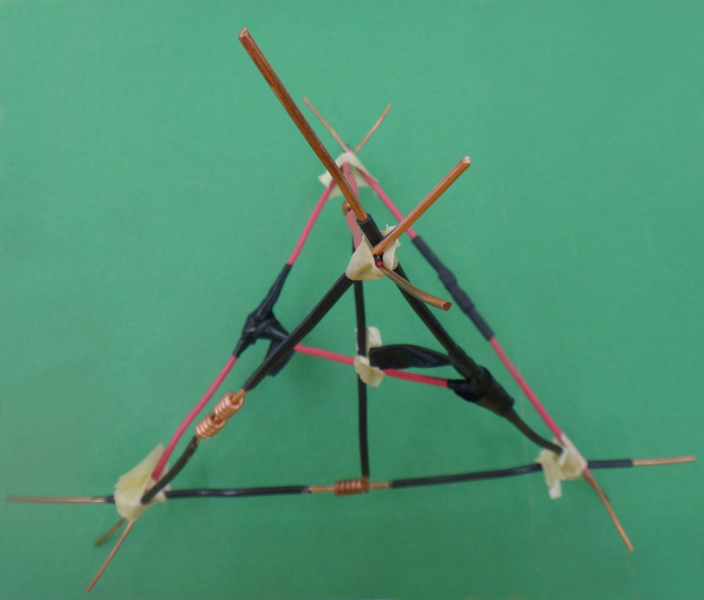
Pyramid Taped
Close-up
Finished

No Marrets

Top

Soldered
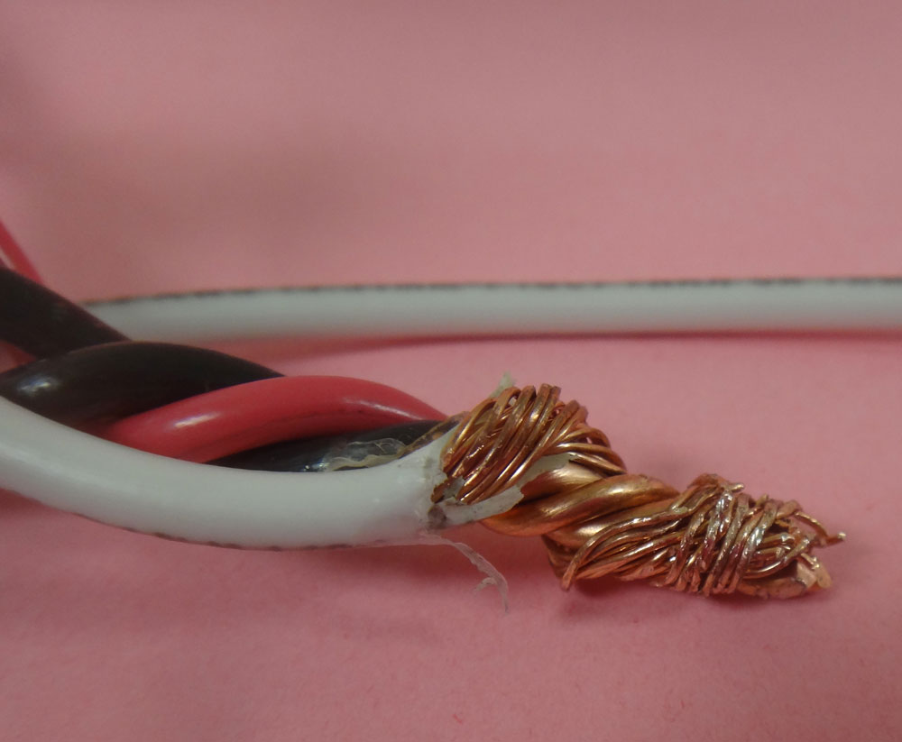
Stranded
Evaluation:
Use the evaluation sheet handout to self and peer mark each step. If you or your peer find something that can be improved upon, you can fill in and update what needs to be done and attempt to fix or re-do prior to the teacher evaluating it. Ensure you are ready and able to explain why you and your peer gave the marks that were assigned. Below is a breakdown of the project marks at a glance:
| Evaluation Breakdown Component Descriptions | Marks |
|---|---|
| Always double check that you have completed all components for full marks. | |
| Wire Stripping - looking for no nicks, 1" stripped off, half knife and half with wire stripper | 26 |
| 2 Western Union Wire Joints - 4-5 turns and tight | 10 |
| 2 T-Tap Wire Joints - 4-5 turns and tight | 20 |
| Soldering 2 joints - Strong, joint fully covered, thin coating | 10 |
| Tinning 2 Stranded Wires -solder thin and strong | 10 |
| Insulation Installation - electrical tape and heat shrink | 10 |
| Pyramid Shape: - temporary tape with ends lining up ready for rat tails | 5 |
| 4 Rat Tail Wire Joints - 4-5 turns and tight with wire connector on loose (for checking) | 20 |
Unit 3, Act. 2: Cable, Boxes, and Devices
Situation:
Wire joints have been practiced and now are ready to work connecting different types of cable, boxes and devices.
Problem/Challenge:
You are connect a receptacle, switch, and light using Romex and armoured cable with a utility, outlet, and octagon box. Cables to be both 2' with 7" of sheathing removed from both ends. While doing this project, you are to learn about common cables, boxes, and devices used in the residential home.
Investigation/Ideas:
Information about what materials are used and how they relate to each other is important. Terms, how to use/connect according to code will help you master your skills in installation of these common electrical components.
Cables
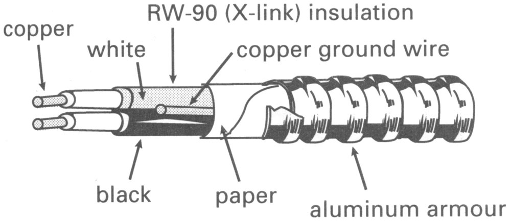
Two common cables used in residential locations are Romex and BX. BX is more common in commercial environments as it has a stronger outer sheathing. Both need to have the outer sheathing removed safely to prevent any electrical shorts. Below is a diagram breakdown showing the parts of an armoured cable. The basic steps to prepare ends of cables properly are as follows:
Nonmetallic Sheath Cable (Romex or NMSC)
- Cable rip, or cut with knife outer sheathing being careful not to cut into the conductor insulation
- Pull back plastic sheathing and cut off
Armoured Cable (AC or BX)
- Cut aluminum sheathing opposite the twist of sheathing, on a 45 degree angle, using a hacksaw to cut through one link fully, being careful not to cut into the paper and conductor insulation
- If you have cut far enough you should be able to crack or break armour to twist off without damaging paper and more importantly the insulated conductors.
- Slide anti-short bushing in place by twisting between sheathing and conductors to protect the conductors from the sheathing, then remove paper
Box cable connections:
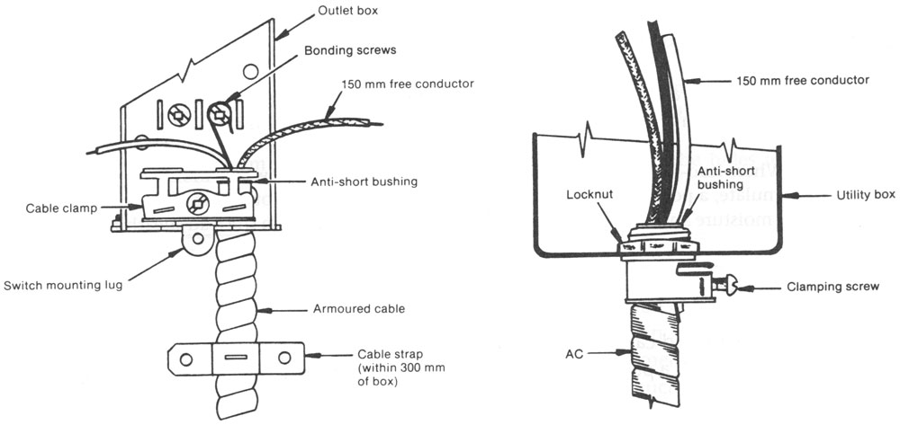 Once the cable sheathing is removed it can now be terminated to a box for safe connection to a device. Here is a diagram of the different types of box terminations and their parts. Hydro code and standards together assure safe termination of cables into boxes. Both the box and the cable must both be certified and installation must also be certified. Materials are certified through organizations such as CSA and inspectors certify the work done to insure that all is safe. Complete the following handout
 ![]() , filling in the blanks and looking at the
, filling in the blanks and looking at the ![]() Hydro code book rules to find the answers to the questions.
Hydro code book rules to find the answers to the questions.
Boxes
There are many different types of electrical boxes used in industry Here are three common electrical boxes found in the home. They all serve a specific purpose. All are made out of galvanized steel with knock-outs for inserting box connectors and some also have internal box clamps for cables to ensure they are safely clamped down. Boxes of any type must not be over filled with wires, devices, etc. For this reason the hydro code has again devised a way to ensure they are not over filled. This handout ![]() helps show how this is done. Take a look at the sample, and then answer the questions on the first page.
helps show how this is done. Take a look at the sample, and then answer the questions on the first page.
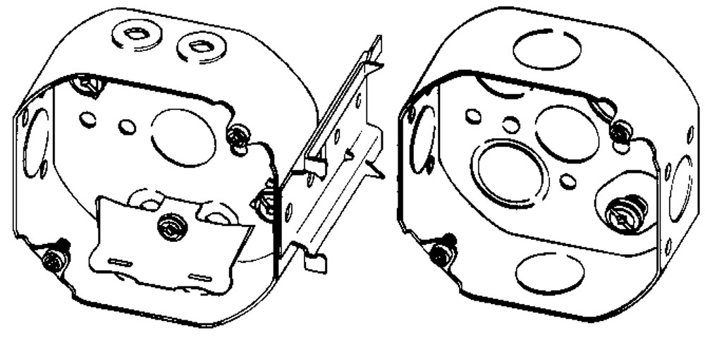
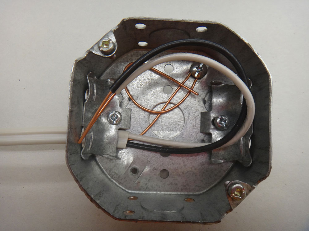
Octagon Boxes
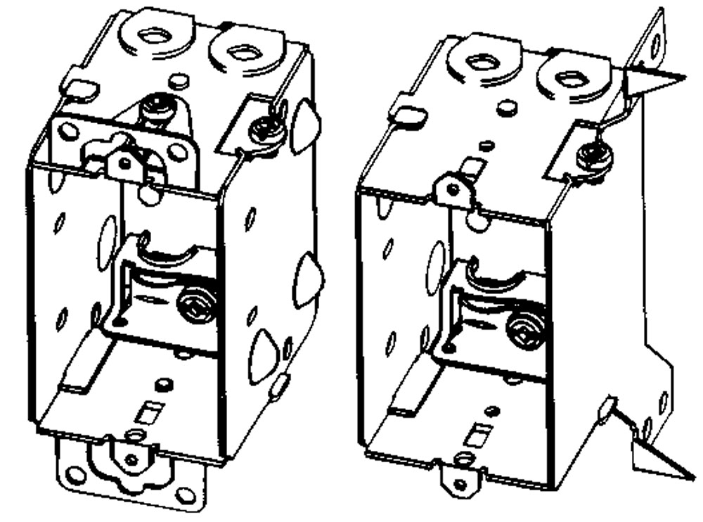
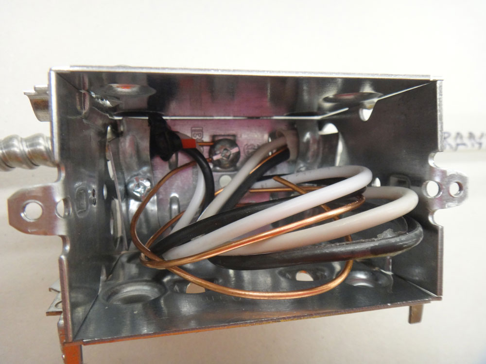
Device Boxes
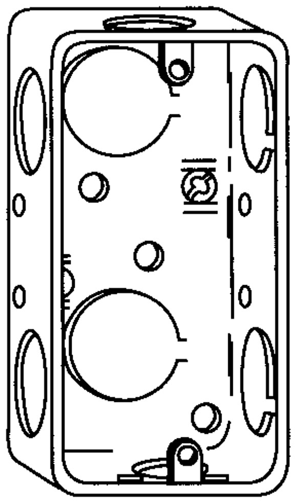
Utility Box
Devices
Each of the devices below have been around for many years and used extensively in the home. Each device has specific parts that should be known for proper connection and operation. Fill in the following handouts with the correct part names:
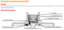
Key-less Incandescent Lamp Holder
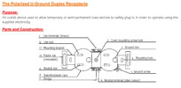
Polarized U-Ground Duplex Receptacle
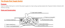
Single Pole Toggle Switch
Create/Construct:
You will be connecting up a lamp, switch, and receptacle in that order to each other. After learning how to remove the sheathing from different cables, you will have to create termination loops to connect to devices. The loop must be clock wise and inserted clockwise under the terminals of the devices you are connecting to. It is important with terminal connections to make sure they are tight by wiggling them after you have initially first tightened them up, then re-tighten to ensure they are tight. Where the insulation ends also is important. Too far/long will expose bare live wires and too close/short will end up under the terminal leaving a bad connection doomed for arcing and later electrical fire.
Major Steps to Follow
- Take two feet of Romex and strip off 6-7" of sheathing at either end, then strip conductors
- Take 18 inches of bx and strip off 6-7" of sheathing at either end, then strip off conductors
- Connect the cables to all three boxes
- Connect all grounds to boxes with U shaped loop and use a marret when two or more grounds come into a box with only the feed cable ground going straight to ground terminal, then connecting to marrret
- Connect the key-less lamp holder to the octagon box wires, with black going to brass terminal screw colour and white going to silver terminal screw
- Connect the SPST switch to the 1104 box black wires and the white are to be marretted
- Connect the receptacle to the third box with wires
Tools and Materials
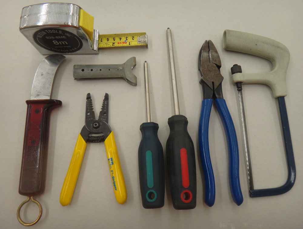
Tools

Materials

Parts - octagon box not shown
Cable Prep and Rough-in
Roughing-in is a term commonly known as connecting the cables to the electrical boxes and tying ground wires to bonding terminals in each of the boxes. Only one ground wire is connected in the device box as the other one is connected by a insulated twist wire connector because it is a more stable joint and limits the "bonding" jumper to stay connected.
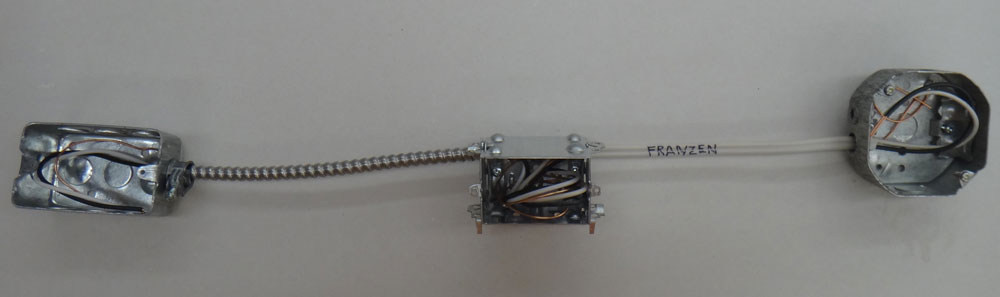
Boxes, cables, wires roughed in.
close-up
Close-up
Device Connections Up Close
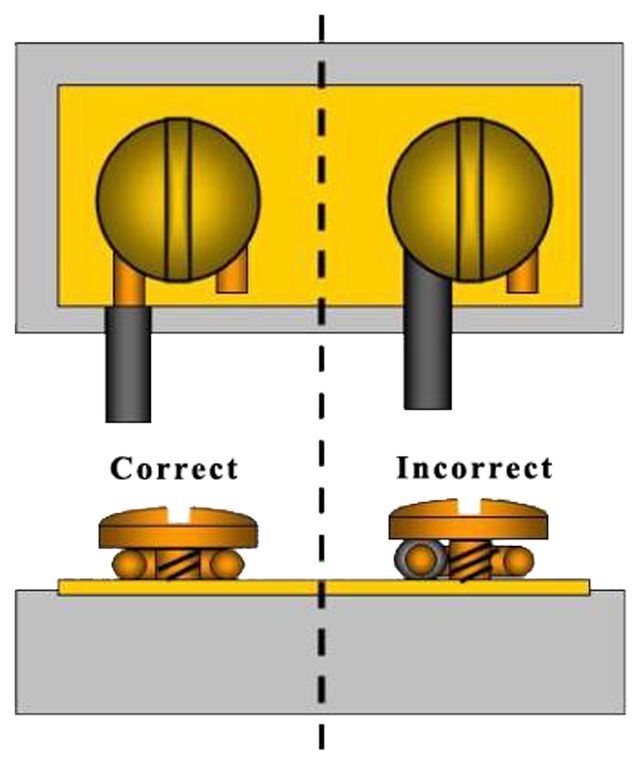
Making terminal connections, it is very important that the wire is bent in the shape of a U so that the terminal screw will seat effectively on it with maximum mechanical and electrical connection. It is important to wiggle and re-tighten, to ensure terminal wire connection will not come apart.

Receptacle
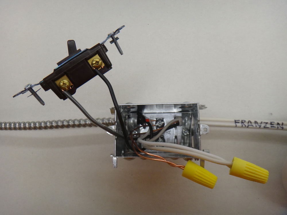
Switch

Lamp
Finished Project
Note tape around receptacle, done as a safety precaution. This can also be done for the switch also.
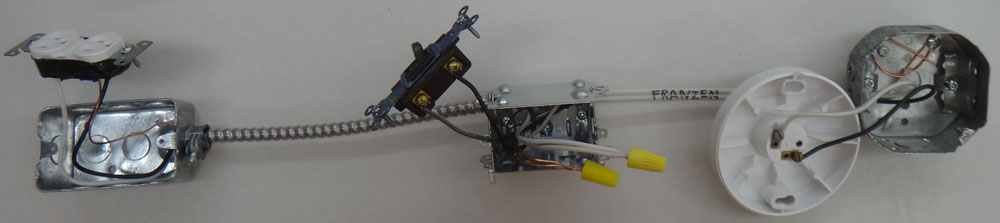
Project showing all devices connected
Evaluation:
Ensure that you have had your work peer marked prior to bringing to teacher for final evaluation.

| Evaluation Breakdown Component Descriptions | Marks |
|---|---|
| Always double check that you have completed all components for full marks. | |
| Romex Cable Stripped - 2' with 6-7" removal of sheath from both ends | 10 |
| BX Cable Stripped - 18" with 6-7" removal of sheath from both ends | 10 |
| Cables Roughed In - all three boxes connected with grounds secured to box terminals | 10 |
| Armoured Cable Box Terminations HO - fill in blanks and questions answered | 15 |
| Maximum # of Conductors in a Box HO - answer all questions with rule numbers | 9 |
| Devices Connected -lamp, switch, and receptacle devices connected properly | 15 |