Unit 3: Residential Electrical Circuits Intro
This unit will introduce you to basic electrical circuits you would find in your home. Common devices such as the receptacle, switch, and lamps installed in common electrical boxes such as the utility, device, and octagon styles will be used. Starting with basic wiring using the right colours, lines, and symbols to design and communicate your electrical circuit through three different types of circuit diagrams.
Getting first hand skills at connecting common devices using cable that is found in the home, learning techniques, and gaining hands-on skills will teach students the basics of home wiring. Making different types of electrical terminations is a critical skill that is important to master to prevent electrical hazards down the road.
Unit Content Activity Quick Links, Click to Jump to Specific Activity!
- Unit 3, Act. 1: Electrical Poster, Proper Wire Preparation, and Connections
- Unit 3, Act. 2: Connecting Cable, Boxes, and Devices
- Unit 3, Act. 3: Residential Wiring Diagrams
 Unit 3, Act. 1: Electrical Poster, Proper Wire Preparation, and Connections
Situation:
As a group of students interested in different technologies, one that is used daily is electricity and devices that help each and everyone of us get through our day. Whether it is your alarm clock in the morning, or the refrigerator we use to keep our food cool, the lights that allow us to see in a dark environment, the speakers that allow us to listen to music, the car that would not be if electricity was not there, and of course the electric motors that turn our lives in many different ways.
Problem/Challenge:
Create a letter sized electrical poster that focuses on three aspects, how it works, safety and energy conservation. The poster should have 75% image graphics and 25% of detailed text related to images and poster topics. For the how-it-works part, you may pick any element related to electricity to show how it works. The practical hands-on component students are to successfully prepare wire ends for connecting properly to each other and devices for both solid and stranded connections as outlined in the Create and Construct section.
Investigation/Ideas:
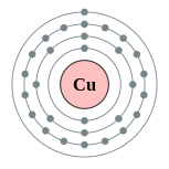
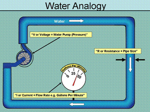
Electrical Theory - How it Works
How electricity works, the theory behind it is important to know, as it is something you can not see, but can be very dangerous if not used properly. The main topics in this handout cover areas such as what electricity is, electron theory, and circuit flow. The following links are some great resources that expand and detail more information about this topic:
- Atomic Structure Of Matter
- Basics of Electricity
- Electron theory
- How Electric Works
- Understanding Electricity

- Bill Nye The Science Guy - Static Electricity
- Bill Nye The Science Guy - Electricity
- The Story of Electricity - Spark (1of3)
- The Story of Electricity - The Age of Invention (2of3)
- The Story of Electricity - Revelations and Revolutions (3of3)
Here are some electrical related facts you might find interesting:
- When birds land on power lines, they don't get electrocuted because they don't represent a path to ground for the electricity If you had an electrical fire and decided to try and put it out with water, because electricity travels at close to the speed of light, it will travel up the steam of water as if that water was standing still.
- Electricity always seeks the easiest and the shortest path to the ground. So if you touch an electrical wire, you become part of the electrical circuit resulting in an instant flow of electricity to the ground
- The fuses in your home prevent fires caused by overloaded circuits, but they do not protect you against shock
Electrical Safety
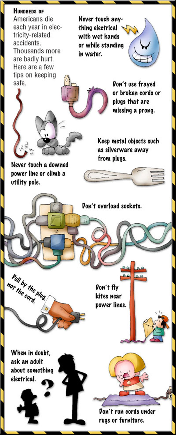
Safety in the home where it comes to anything related to electric, standards must be high for components that use electricity, and if not familiar with the dangers, people can be hurt or worse, die from improper use and/or handling. The following links will detail some safety issues everyone needs to be aware of in the home when using electricity.

- Shock current path
- Electricity FAQs
- The Fatal Current
- Electrical Safety - Basic Information
- Electrical Safety at Home
- 15 Safety Precautions
- 21 Safety Rules
- Wrong Way Right Way: Safety Cases
- 10 Shocking Facts About Electrical Safety by ESA
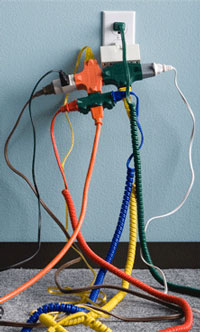
There are a lot of safety concerns to be aware of related to electricity. For example, here are some safety points about the use of outlets:
- Use only equipment that is properly grounded or double-insulated;
- Do not overload outlets;
- Do not plug multi-outlet bars to other multi-outlet bars;
- Only use equipment that has been approved by a national testing laboratory;
- Minimize the use of extension cords. Do not plug two extension cords together;
- Do not cover power cords or extension cords with rugs or mats;
- Do not run electrical cords through pedestrian aisles;
- Unplug or disconnect machines before servicing or repairing;
- Do not ignore the warning signs. If an item feels hot, makes an unusual noise (buzz or hum), smokes or sparks, take it out of service immediately and tag it "Do Not Use";
- Inspect cords and equipment regularly, and report any defects immediately;
- Cover or guard any exposed electrical components or wires;
- Unplug cords from the outlet by gripping the plug. Do not pull the cord;
- Do not use electrical equipment or appliances near water or wet surfaces;
- Never use electrical equipment when hands or the equipment are wet
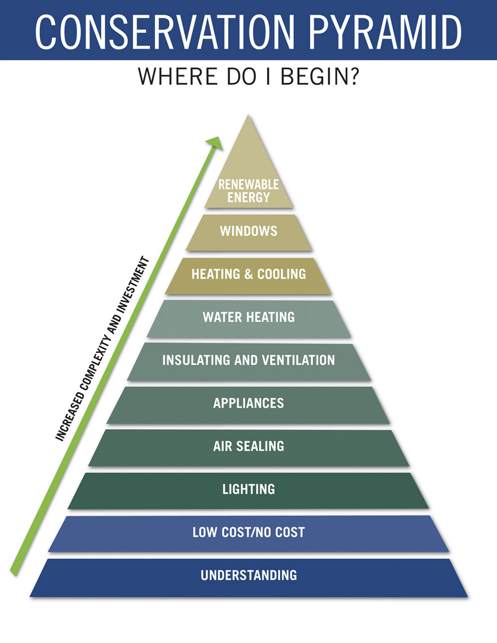
Electrical Energy Conservation
Safety in the home where it comes to anything related to electricity, standards must be high for components that use electricity, and if not familiar with the dangers, people can be hurt or worse, die from improper use and/or handling. The following links will show some safety issues everyone needs to be aware of in the home when using electricity.

- Detect Energy
- Energy Conservation in the Home
- 21 ways to conserve electricity
- Energy conservation measures
- Reduce your electricity consumption
- Residential Conservation Programs
- Lets Save Electricity At Home
- The Energy Efficient House
- Energy Conservation Techniques to Save on Your Home
Wire Stripping
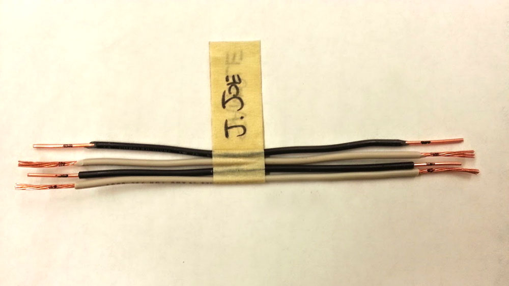
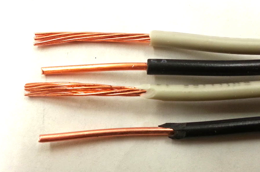
Below are some pictures of wire stripping up close. Review the Wire Sizes and Stripping hand-out before attempting what looks like a simple task, but actually has some important points that you need to be aware of prior to completing this task. Look closely at the way the insulation is removed and note the lack of nicks in the cooper wire.
Wires Stripped
Up-Close-Knive & Stripper
Terminal/Rat-tails
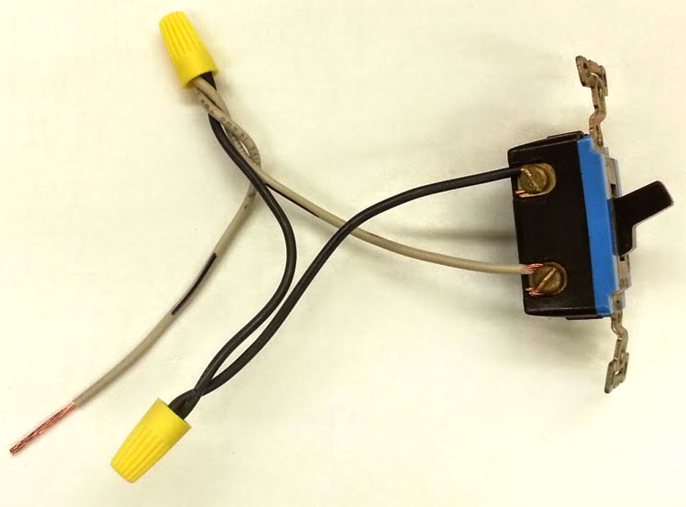
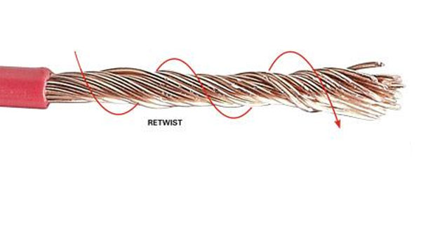
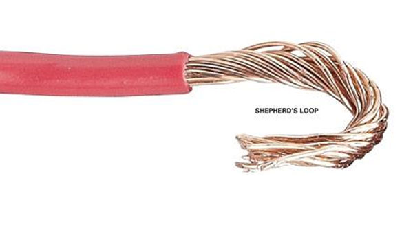
Terminal Wire Connection with Shepherd's Loop with Stranded Wire
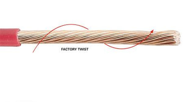
Making a shepherd's loop with solid wire is considerably easier than stranded wire. The key to making both is to loop it the same direction as the terminal screw goes to tighten it. The following images show how to properly twist stranded wire to ensure when the screw terminal is tightened, the twist of the strand and the direction
Shepherd Loop Step 1
Shepherd Loop Step 2
Shepherd Loop Step 3
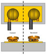 Terminal Wire Connection with Shepherd's Loop
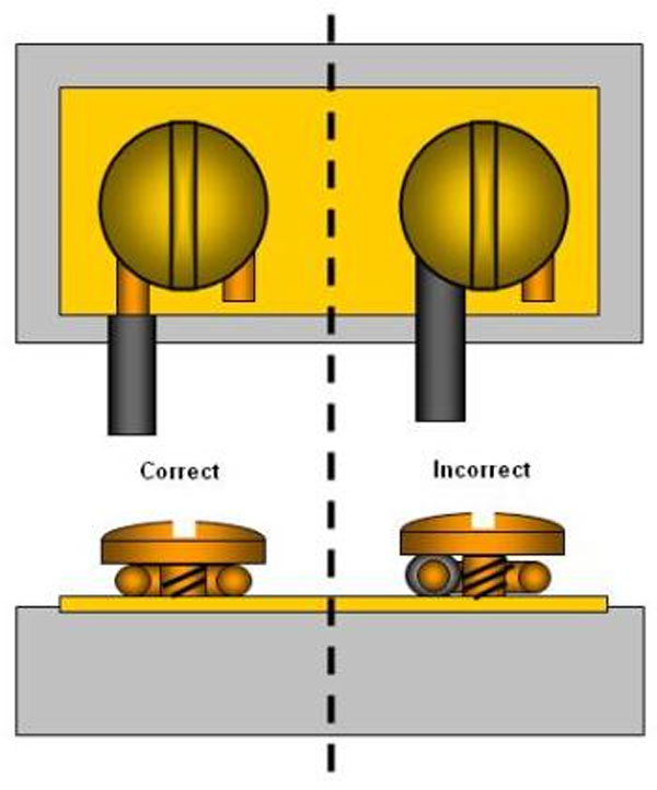
When connecting a wired loop connection it is critical that the loop be going in the same direction as the screw terminal is turning. Most screws turn clockwise to tighten so your loop should be also looped around the screw terminal in a clockwise direction. This is done so that when the terminal screw is tightened, the shepherd's loop will be naturally pulled in tighter to the centre of the terminal. If it was looped counter-clock-wise, the tendency would be to widen the loop making it poor connection.
Create/Construct:
Follow the steps below to get started learning about electricity, safety, conservation, and wire joints.
- INTRODUCTION: Read the Electrical Theory Handout and answer the questions at the end in the space provided
- POSTER: Review the electrical theory resources and then electrical safety in the home, and create a letter sized poster using Illustrator or similar program
- Focus on two related themes that show how electricity works and how to safely handle situations and/or devices that use electricity
- ACTIVITY: Using 14 AWG solid and stranded demonstrate and complete two 8" lengths of solid wire, 1" stripped with a knife, one with a pair of wire stripper pliers, and also two with stranded wire
- One of the 8" lengths for both the solid and stranded will be used to continue making a shepherd's loop on one end, then attaching both to single residential device with two terminals
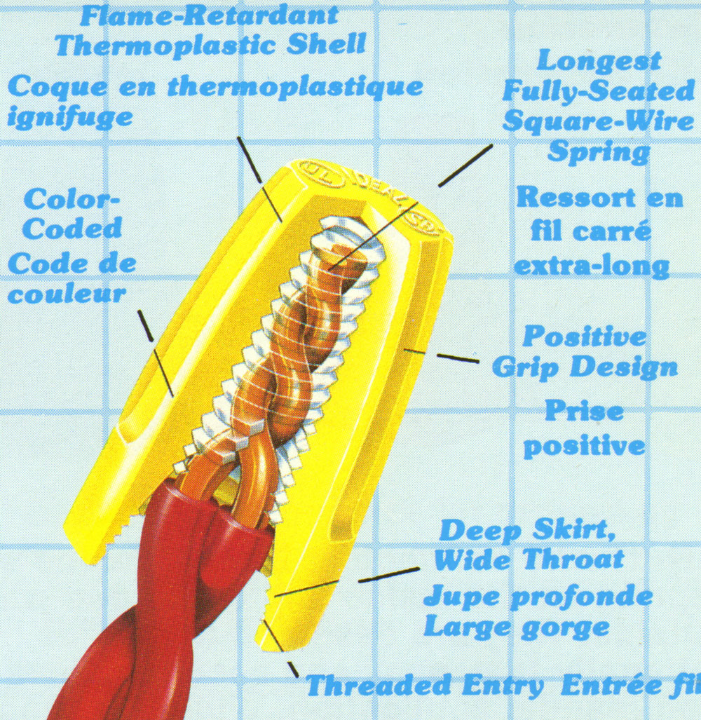
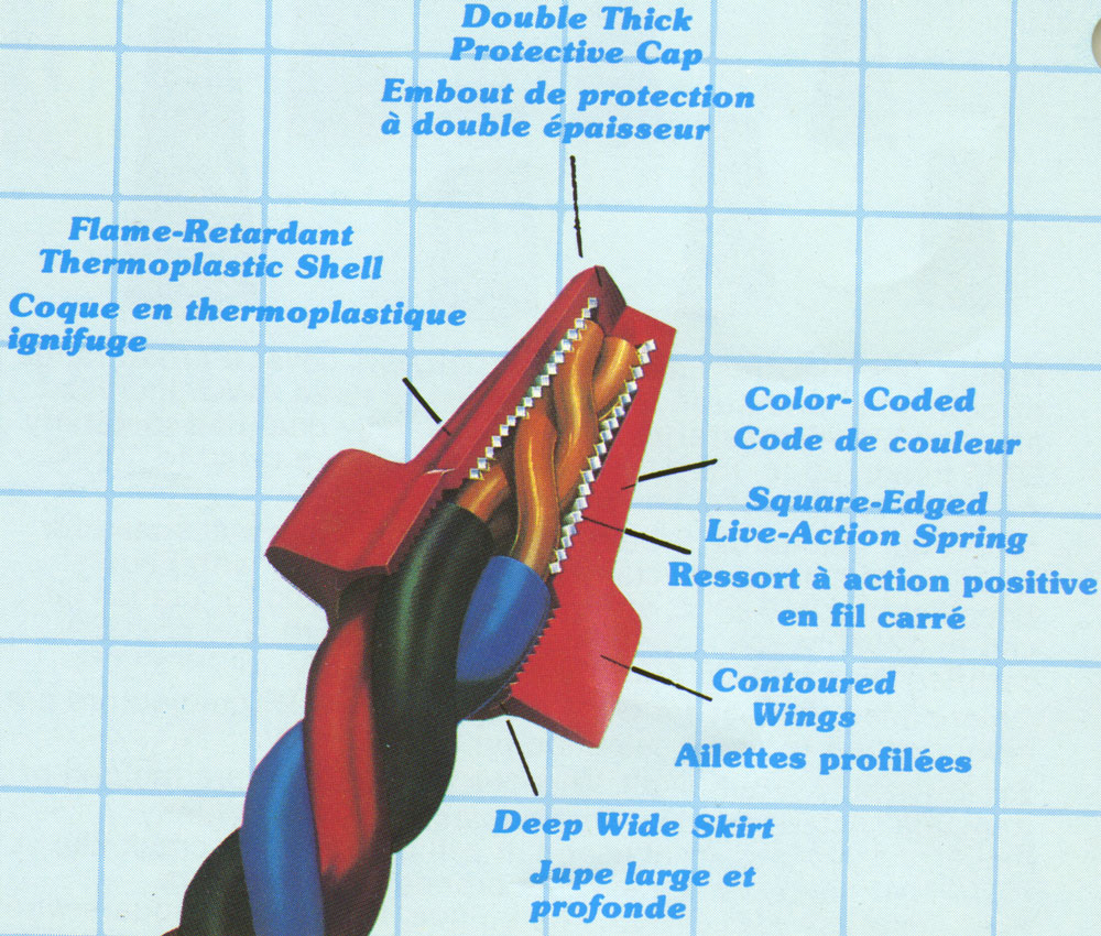
- Once you have created a total of four 8" lengths, two solid wires will be twisted together to make a 2 wire rat tail, the straight end of the solid will be twisted together with the other two stranded wires to create a 3 wire conductor rat tail, both connected by a solderless wire connector size 33 and 35 marret
Evaluation:
Ensure that you have included all required drawing components for full marks.
| Evaluation Breakdown Component Descriptions | Marks |
|---|---|
| Always double check that you have completed all components for full marks. | |
| Electrical Theory- Six review questions answered neatly in sentence form | 15 |
| Electrical Poster- Letter size, electricity, safety, & energy savings with 75% images, 25% text | 20 |
| Wire Stripped - 4 #14 AWG wires, 8" each, 2 with Knife and 2 with pliers, 1" and no nicks | 20 |
| Shepherd's Loop- size, fit, direction of loop and under terminal- stranded/solid | 10 |
| Wireless Connector- neatly twisted, tight, no cooper showing, joint solid - stranded/solid | 10 |
Unit 3, Act. 2: Connecting Cable, Boxes, and Devices
Situation:
Wire joints have been practiced and now are ready to work connecting different types of cable, boxes and devices.
Problem/Challenge:
You are connect a receptacle, switch, and light using romex and armoured cable with a utility, outlet, and octagon box. Cables to be both 2' with 7" of sheathing removed from both ends. While doing this project, you are to learn about common cables, boxes, and devices used in the residential home.
Investigation/Ideas:
Information about what materials are used and how they relate to each other is important. Terms, how to use/connect according to code will help you master your skills in installation of these common electrical components.
Cables
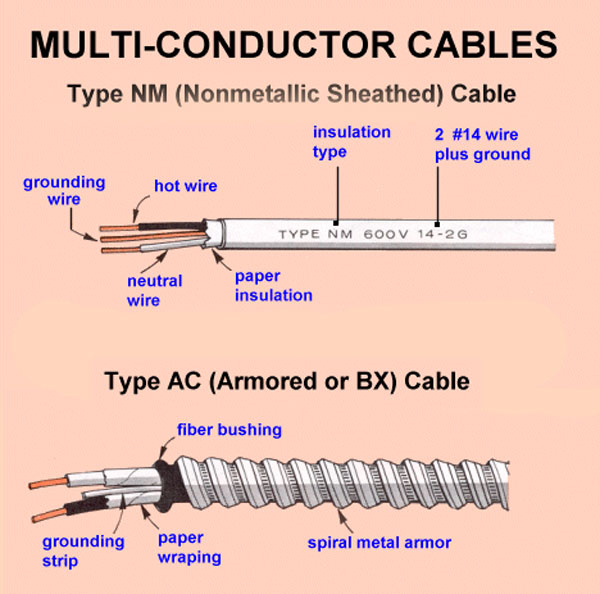
Two common cables used in residential locations are Romex and BX. BX is more common in commercial environments as it has a stronger outer sheathing. Both need to have the outer sheathing removed safely to prevent any electrical shorts. Below is a diagram breakdown showing the parts of an armoured cable. The basic steps to prepare ends of cables properly are as follows:
- Nonmetallic Sheath Cable (Romex)
- Cable rip, or cut with knife outer sheathing being careful not to cut into the conductor insulation
- Pull back plastic sheathing and cut off
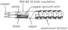
- Armoured Cable (BX)
- Cut aluminum sheathing on a 45 degree angle with hacksaw to cut through one link, careful not to cut into insulation
- If you have cut far enough you should be able to crack or break armour and twist off
- Slide anti-short bushing in place by twisting between sheathing and conductors to protect the conductors from the sheathing, then remove paper

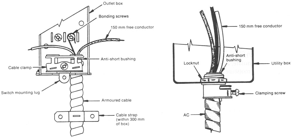 Once the cable sheathing is removed it can now be terminated to a box for safe connection to a device. Here is a diagram of the different types of box terminations and their parts. Hydro code and standards together assure safe termination of cables into boxes. Both the box and the cable must both be certified and installation must also be certified. Materials are certified through organizations such as CSA and inspectors certify the work done to insure that all is safe. Complete the following handout
 ![]() , filling in the blanks and looking at the
, filling in the blanks and looking at the ![]() Hydro code book rules to find the answers to the questions.
Hydro code book rules to find the answers to the questions.
Boxes
There are many different types of electrical boxes used in industry Here are three common electrical boxes found in the home. They all serve a specific purpose. All are made out of galvanized steel with knock-outs for inserting box connectors and some also have internal box clamps for cables to ensure they are safely clamped down. Boxes of any type must not be over filled with wires, devices, etc. For this reason the hydro code has again devised a way to ensure they are not over filled. This handout ![]() helps show how this is done. Take a look at the sample, and then answer the questions on the first page.
helps show how this is done. Take a look at the sample, and then answer the questions on the first page.
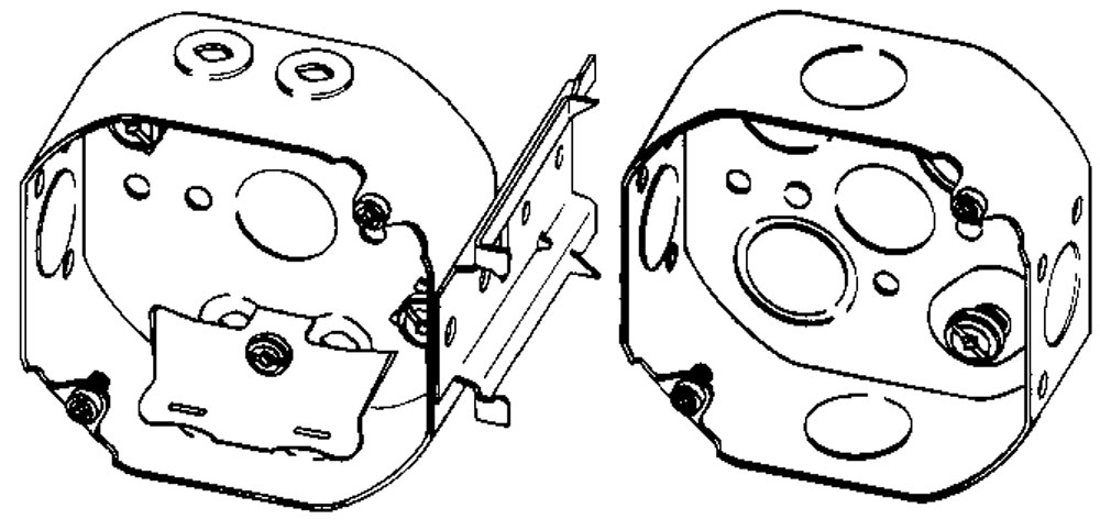
Octagon Boxes
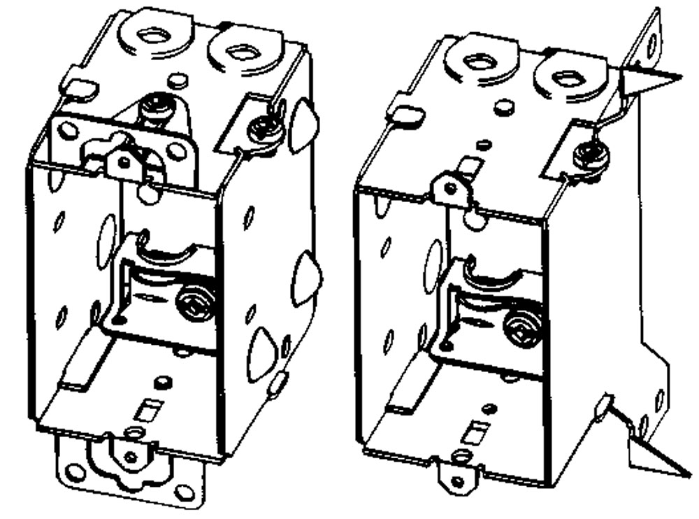
Device Boxes
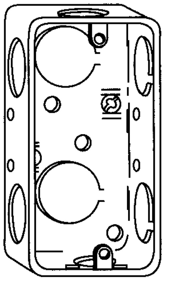
Utility Box
Devices
Each of the devices below have been around for many years and used extensively in the home. Each device has specific parts that should be known for proper connection and operation. Fill in the following handouts with the correct part names:
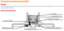
Keyless Incandescent Lamp Holder
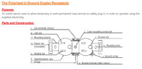
Polarized U-Ground Duplex Receptacle
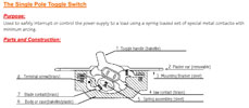
Single Pole Toggle Switch
Create/Construct:
You will be connecting up a lamp, switch, and receptacle in that order to each other. After learning how to remove the sheathing from different cables, you will have to create termination loops to connect to devices. The loop must be clock wise and inserted clockwise under the terminals of the devices you are connecting to. It is important with terminal connections to make sure they are tight by wiggling them after you have initially first tightened them up, then re-tighten to ensure they are tight. Where the insulation ends also is important. Too far/long will expose bare live wires and too close/short will end up under the terminal leaving a bad connection doomed for arcing and later electrical fire.
Major Steps to Follow
- Take two feet of romex and strip off 7" of sheathing at either end, then strip conductors
- Take two feet of bx and strip off 7" of sheathing at either end, then strip off conductors
- Connect the cables to all three boxes
- Connect all grounds to boxes, use marret when two or more grounds come into a box
- Connect up the lamp holder to the octagon box wires
- Connect up the switch to the box wires directly connected to the octagon box
- Connect up the receptacle to the third box with wires
Tools and Materials
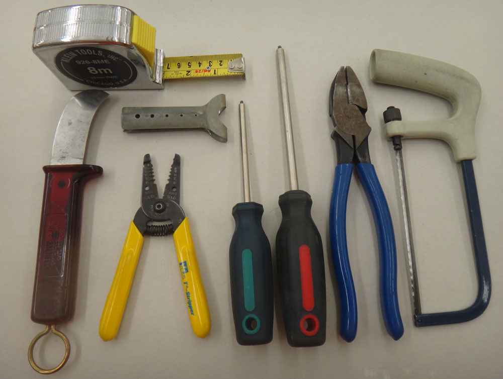
Tools

Materials

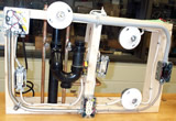
Parts - octagon box not shown
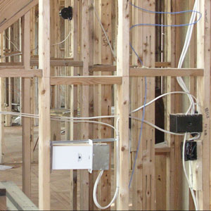
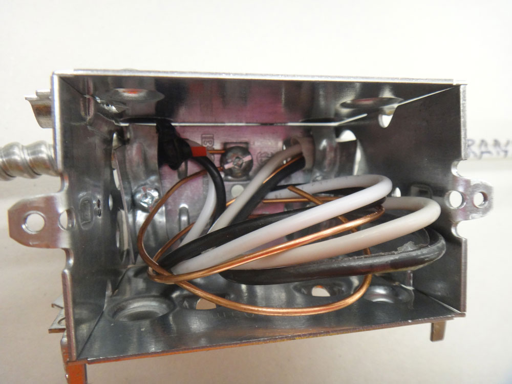
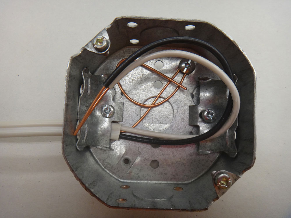
Cable Prep and Rough-in
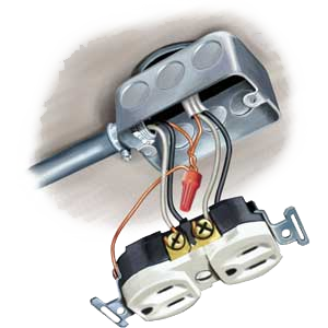
Roughing-in is a term commonly known as connecting the cables to the electrical boxes and tieing ground wires to bonding terminals in each of the boxes. Only one ground wire is connected in the device box as the other one is connected by a insulated twist wire connector because it is a more stable joint and limits the "bonding" jumper to stay connected.
Boxes, cables, wires roughed in.
close-up
Close-up
Device Connections Up Close
Making terminal connections, it is very important that the wire is bent in the shape of a U so that the terminal screw will seat effectively on it with maximum mechanical and electrical connection. It is important to wiggle and re-tighten, to ensure terminal wire connection will not come apart.

Receptacle
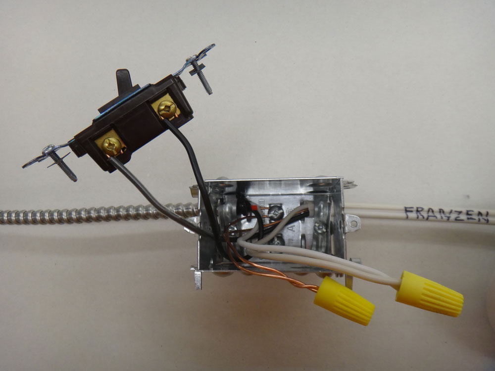
Switch

Lamp
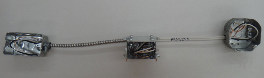
Finished Project
Note tape around receptacle, done as a safety precaution. This can also be done for the switch also.
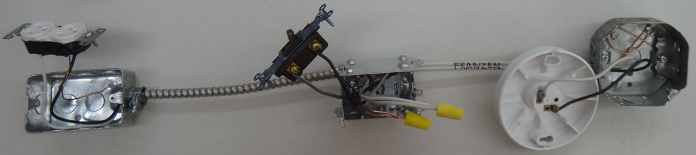
Project showing all devices connected
Evaluation:
Ensure that you have had your work peer marked prior to bringing to teacher for final evaluation.
| Evaluation Breakdown Component Descriptions | Marks |
|---|---|
| Always double check that you have completed all components for full marks. | |
| Romex Cable Stripped - 2' with 7" removal of sheath and conductors stripped | 10 |
| BX Cable Stripped - 2' with 7" removal of sheath and conductors stripped | 10 |
| Cables Roughed In - all three boxes connected with grounds secured to box terminals | 14 |
| Devices Connected -lamp, switch, and receptacle devices connected properly | 14 |
Unit 3, Act. 3: Residential Wiring Diagrams
Situation:
As with any type of construction project, each has a simplified and detailed way to communicate what needs to be done to finish the related trade construction task. Each trade works with different symbols, lines, and related code to get the job done.
Problem/Challenge:
Using three types of electrical wiring diagrams, namely: symbolic/flow, schematic/line, and layout/pictorial, neatly draw working common residential electrical circuits taking into account the hydro Code and trade standards. Use appropriate symbols, pictorials, and lines in pencil to create wiring diagrams and use colours for actual conductor wires. You will also need to create an estimate of how much the circuit components would cost if you were to go out and purchase each of the electrical components need to build that electrical circuit.
Investigation/Ideas:
You will need to get yourself four colours preferably green (ground), blue (neutral/identified), black (primary power), red (secondary power). You will use a pencil to create the symbols and pictorials of the boxes, devices, and cables There are a number of areas that need to be reviewed in-order to accomplish this::
- Symbols and basic illustrations
- Line types drawing conventions
- Circuit and device connections
- Current flow of electricity
- Operation of devices
- Hydro Code
- Electrical Standards
Here are some resources that can be used to help with understanding how the above points relate and are used to wire up residential circuits.
- 2012 Residential Wiring Guide

- Hydro code rules
- Understanding electrical symbols for house wiring
- Electrical symbols
- Wiring diagrams 1
- Wiring diagrams 2
- Wiring diagrams 3

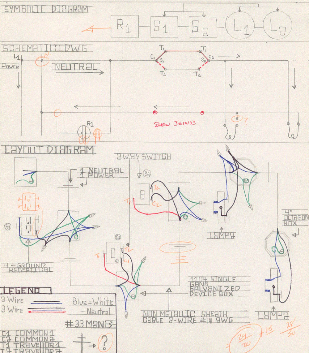
There are three different types of wiring diagrams you will need to familiarize yourself with:
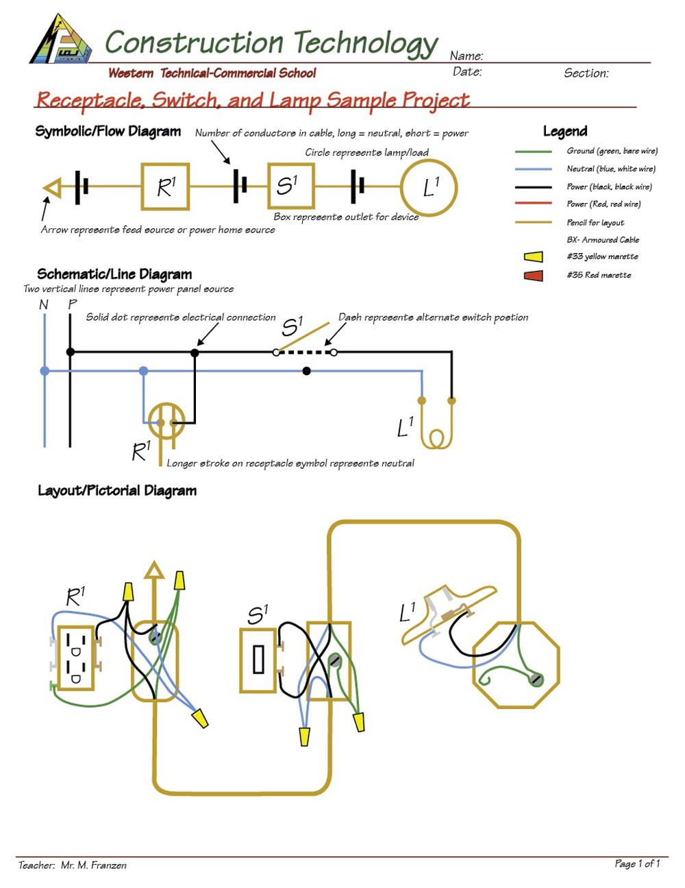
Symbolic/flow Diagrams (The What)
Simplest diagram shows what devices are connected through identified boxes and circles
- Most simple wire/device relationship
- Simple rectangles and squares
- Labels using subscript
- Usually single line
- Similar to one line blueprint electrical circuits
Schematic/line Diagrams (The How)
Efficiently shows exactly how everything is connected electrically using lines and symbols
- Most detailed and easy to follow diagram
- Simple symbolic device representation
- Straight Lines connecting devices
- Crossing lines have dot if connected
Layout/Pictorial Diagrams (The Where)
Realistically shows where boxes and devices are located and all actual physical wiring connections.
- Most realistic of the three diagrams
- Devices drawn similar to what they look like
- Wire connections physically shown
- Cables types and details
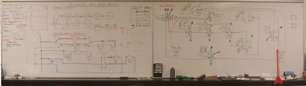
Here are some samples drawings done by students in the past:
Sample 1
Sample 2
Sample 3
Create/Construct:
3 Device Project Sample
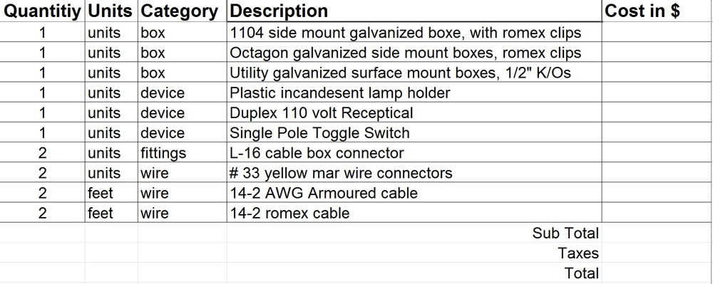
Using your recently 3 device wiring project, draw out the three different wiring diagrams based on how it is wired with the feed coming in from the bottom box used for the receptacle showing all conventions shown in sample. You are to also create a ![]() cost sheet on how much each your project costs by going out to a local hardware store or online supplier and pricing out each of the materials including sub totals and final total.
cost sheet on how much each your project costs by going out to a local hardware store or online supplier and pricing out each of the materials including sub totals and final total.
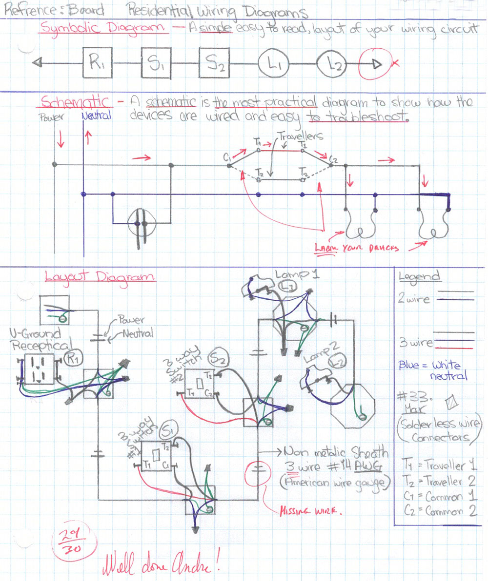
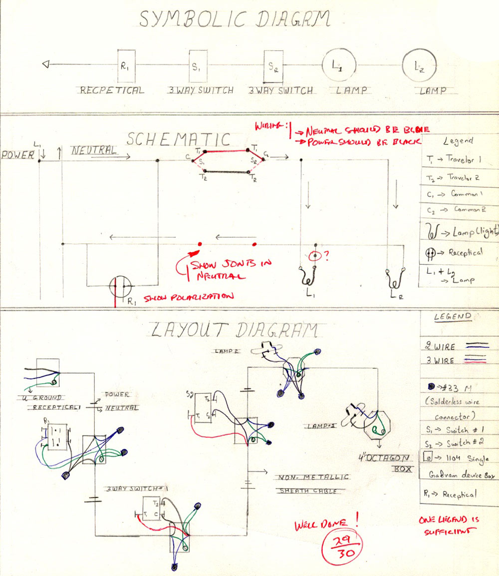
CCT 1- Split Receptacle Switched with 2 Lamps Switched From 2 Locations
Design a circuit which has two receptacles, with one switched by a single pole switch. Two lights are to also be controlled by two three way switches from two different locations. Also you are to find 5 hydro code rules for the following issues prior to construction of your project.:
- How high to mount a receptacle box?
- How high to mount a switch box?
- Where to support cables?
- How long must conductors be in a outlet box?
- What size breaker are you to use for this circuit?
Below are three resource sheets related to the above two projects

Evaluation:
Ensure that you have included all required drawing components for full marks.
| Evaluation Breakdown Component Descriptions | Marks |
|---|---|
| Always double check that you have completed all components for full marks. | |
| 3 Device Wiring Diagram - 1 page, 3 diagrams, pencil, colours, legend, neat, labels | 15 |
| 3 Device Cost - Cost sheet price breakdown | 10 |
| Split Recpt Switched with 2 Lamps Switched 2 Locations - same marking criteria as above | 30 |
| Hydro Code Rules -submit list rule # and explanation for each | 10 |