
Unit 2: Bridging the Gap in the Design Process
This unit will take you through the SPICE design process in a little more detail. You will need to depend on each of the steps in order to accomplish your goals throughout this unit. The first unit will focus on ideas, research and presentation. The second unit, you will learn how to illustrate your bridge design on the computer, and the last unit will focus on the building of your Bridge design.
Unit Content Activity Quick Links, Click to Jump to Specific Activity!
- Unit 2, Act. 1: What is a Truss Bridge?
- Unit 2, Act. 2: Illustrating Your Final Bridge Design
- Unit 2, Act. 3: Building Efficiency
 Unit 2, Act. 1: What is a Truss Bridge?
Situation:
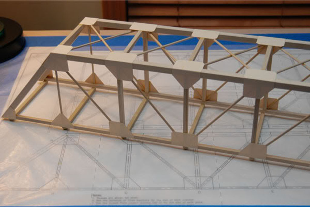
We are a group of students who have looked at and practiced how sketching and the design process work in a technological field and are ready to apply this knowledge and experience to the task of designing and building the most "efficient" bridge. For this reason we will need to go through three major steps/goals with the first one being "What is a truss bridge?" in relation to our final task which is to build one.
Problem/Challenge:
In groups of two you are to research, present, and then independently design 4 different truss style bridge designs with a goal of maximizing the efficiency of the bridge. You will receive wooden pieces 5 * 5 mm thick, 8 at 610 mm long (approximately 9 grams each) and one at 380 mm long. The wood material is made of bass wood, very similar to balsa wood, also commonly used for model bridge building. The bridge must be kept under a weight of 150 grams and adhere to full scale drawing template. See Rules below for more details.
Investigation/Ideas:
 All steps of the SPICE process are important, but this step is very important in order to prepare you before your build. If this step is not done thoroughly, you will end up with a poor or bad finished product. The more work you put in this step will pay off in dividends with your final product. Rules below were written up based on using 1/8" * 1/8" strips and is in imperial measurements, so a little adjustment to the sizes will be tolerated. You may need to convert some measurements, so knowing that 1" equal to 25.4 mm, will allow you to calculate the conversion. If you are unsure of a rule, ask!
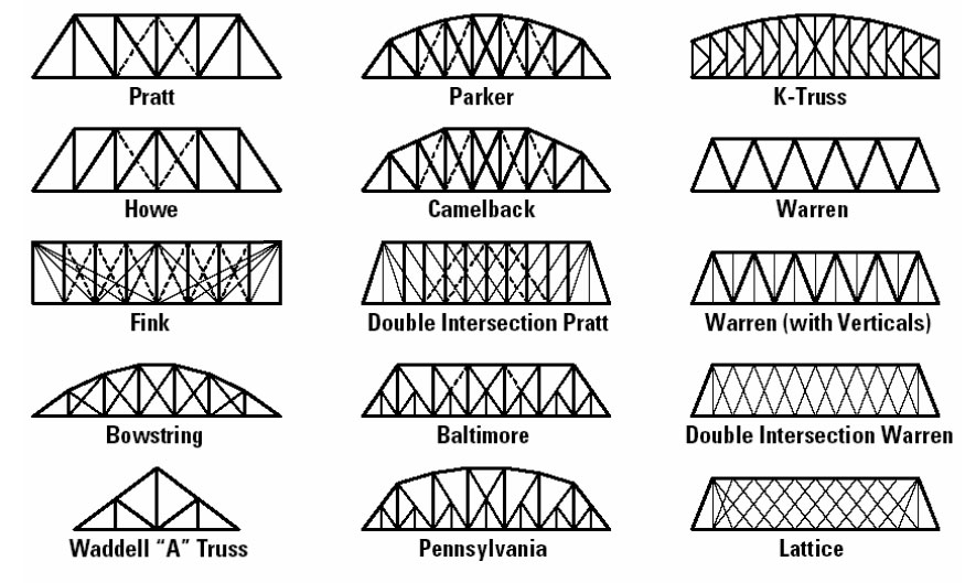
Common Trusses
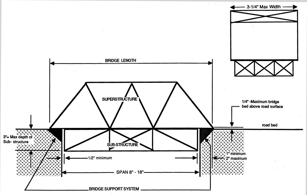
Bridge Terms

Rules 1

Rules 2
Research
Select one area with your group to create a 8 to10 page Power Point presentation to show related information to truss bridge design and building:
- History of Bridges
- Types and Variations of Truss Bridges
- Civil Engineers - skills, knowledge, education
- Bridge Terminology and Explanations
- Bridge Physical Design Principles
- Wooden Bridge Build Ideas and Techniques
- Building the the Most Efficient Wooden Truss Bridge
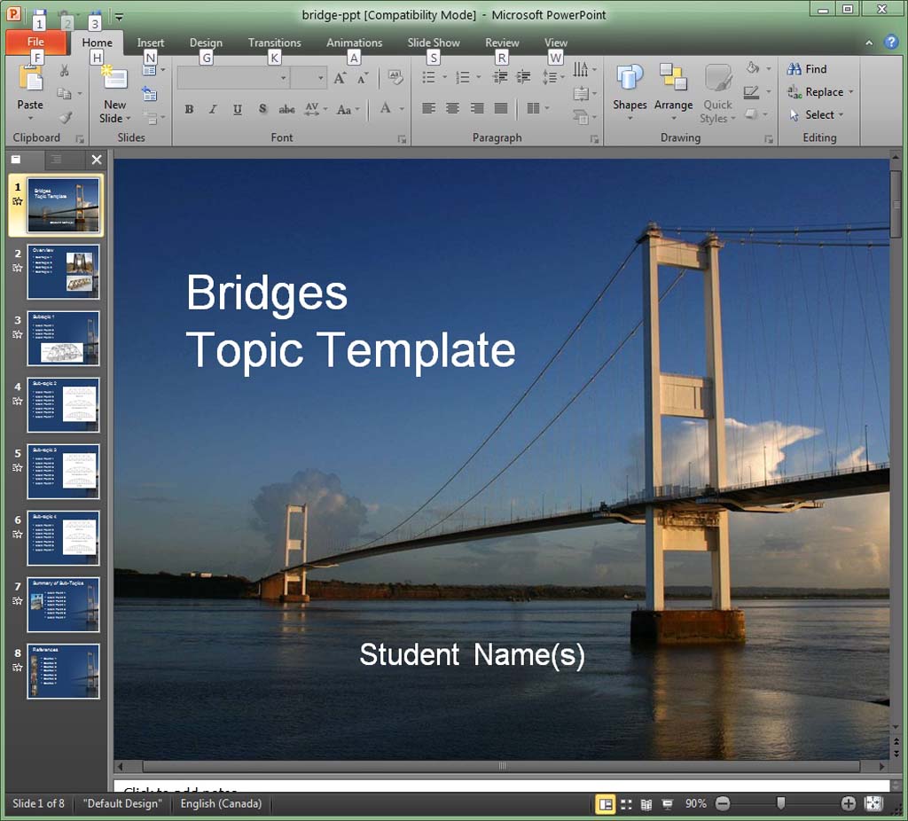
Power point presentations must include a title page and reference page showing all major sources and include 50% graphics/illustrations. Power Point is a program that allows you to show your ideas through slide show screens. If you have never used Power Point, but have used Microsoft Word, then you are half way there, as they are similar. For more information on the program click on one of the following links:
- Introduction to Power Point 2003
- Introduction to MS Power Point 2003 Video
- Introduction to Power Point Site
- In-depth look at Power Point 2003 PDF
- TemplatesWise.com
- Indezine Templates
- Microsoft Templates
- Presentation Magazine
-
 Power Point Sample
Remember to keep your points short and to-the-point, use large print and include graphics. See some online bridge slide shows here ![]() .
.
Resources
Below are a number of related online links you could use to start your research:
- Wikipedia Bridge Info
- Bridge Basics
- How Bridges Work
- Elements of Bridge Design
- Bridge Construction Overview
- Bridge History
- Bridge Building Simulation
- Bridge Dictionary
- Structures and Shapes
- Bridge Terminology
- Bridge Engineering Software
- Bridge History Time line
- Building BIG Bridges
- Garretts Bridges
- 5 Steps to building Bridges

- Model Bridge Destruction
-
 Balsa Wood Bridge: 202 Pounds
 - Tips on a Popsicle Stick Bridge
- Bridge Project
- Balsa Wood Bridge
- Make a good balsa wood bridge
- Balsa Wood Bridge: 202 Pounds
- Bridge Theory
- Bridge Collapse News
Create/Construct:
 Research
Once your group has their topic and understands the direction and purpose of your topic, break it down into 4 to 6 related sub-topics. You might have to do this while you are looking up your information. Suggest you put your information directly into Power Point Your major points should accompany points written down in the notes section of each slide so that you can verbally expand on your major points. Each sub-topic page must have a image taking about 50% of the page. In general your Power Point should be broken down into the following sections:
- Title Page
- Overview
- 4 to 6 pages showing 4-6 sub-topics
- Summary/conclusion
- References/sources of information
Topic information in your presentation must keep your final project in mind, so that everyone will have enough pertinent information to sketch 4 working truss bridge designs.
Presentation
Each group will present based on a random draw. The first three groups that volunteer to go first will get a bonus 3,2,& 1. Each presentation should be shared in operating slides and discussing points on each slide. The presentation should be between 5 - 7 minutes, not including questions and discussion after the presentation. Groups should show knowledge of their topic, answer questions based on their topic, speak clearly, and have a great slide show.
Bridge Design Sketches
After listening to all groups presentations, sketch out 5 different working truss bridge designs using supplied template graph sheet. You are to show 4 orthographic views top, bottom, front, and right side of bridge design. Make sure you are using a pencil and show how all of your pieces would connect. Add any notes you feel relevant to each of your designs.
Sketching Handout

Sample 1
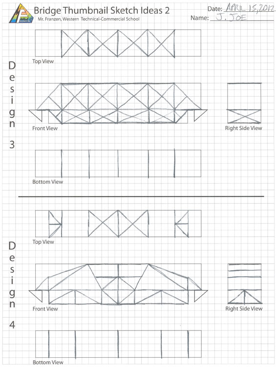
Sample 2
Evaluation:
Marks will be earned for your researched information, your presentation and your 4 sketched bridge designs.

| Evaluation Breakdown Component Descriptions | Marks |
|---|---|
| Always double check that you have completed all components for full marks. | |
| Researched Information - on topic, accurate, 4-6 sub-topics + notes, & references | 20 |
| Power Point Presentation - communication, topic-information, pictures, 5-7 min. | 10 |
| Orthographic Sketched views - 4 ortho views, sketch details, and related notes | 20 |
Unit 2, Act. 2: Illustrating Your Final Bridge Design
Situation:
Peer Power Point presentations and sketches should have helped you and your partner to understand what what kind of bridge would be relatively strong and support a lot of weight relative to the weight of the bridge itself (efficiency). Knowledge about bridge design, types of trusses, history of bridges, how to get the best efficiency, wooden build techniques, and wood joints are all important when finalizing your bridge design.
Problem/Challenge:

The next step of this activity is to finalize your design with a full size drawing using Illustrator. Select your best design(s) and accurately draw out your design using a supplied template in Illustrator. Final bridge testing will take into account the efficiency of your bridge.
Find your theoretical (technical guess) efficiency by taking the weight your bridge will support prior to breaking and dividing that by the weight of your bridge (keep the units the same, that is why we multiply the pounds of weight your bridge can hold by 454 to get the total grams).
![]() Each of your full length pieces (610 mm) of wood are about 9 grams each, so you can calculate approximately how heavy your bridge is and how much weight you hope to hold.
Each of your full length pieces (610 mm) of wood are about 9 grams each, so you can calculate approximately how heavy your bridge is and how much weight you hope to hold.
Investigation/Ideas:
Things to Keep in Mind
Finalizing and selecting your end design is very important. Efficiency of the bridge is the most important goal of your design. Some important points to keep in mind:
- Both super-structure, road bed and sub-structure may be used
- Triangles are much stronger than four sided figures
- Bridge span must have ten mm gap from support system
- Template shows maximum length, width, and height
- Bridge width must be full width to fit test block
- Ten mm maximum above road bed surface (top of bridge support system)
- Laminations may be done in accordance to TSA rules
- Review peer Power Point presentations for more ideas
Design Terms and Explanation
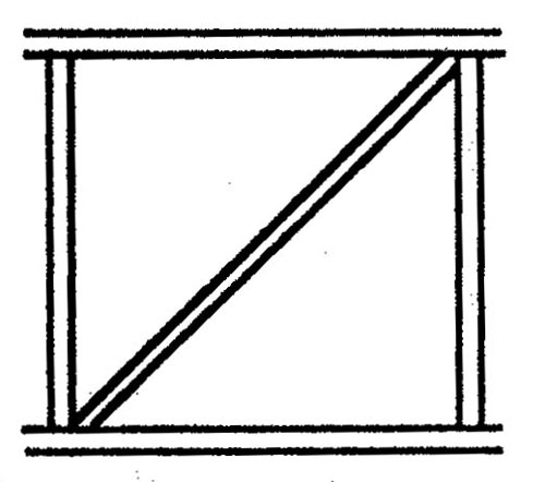
When a load is placed in the middle of a beam, it tries to compress on the top creating what is called compression and the bottom tries to pull apart which is known as tension. Racking is a stress that naturally distorts a square or rectangle into a parallelogram from weight above. By putting a diagonal brace in the middle, corner to corner, you get two triangles, which are the strongest possible shape
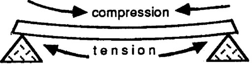
Load, Compression, and Tension
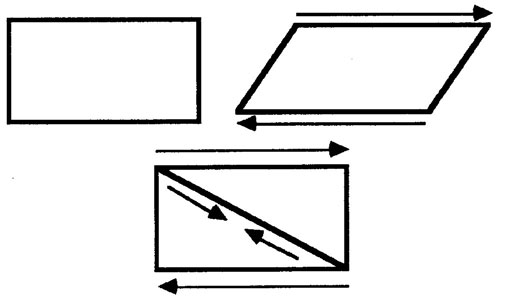
Racking and Stiffening
Design Loads
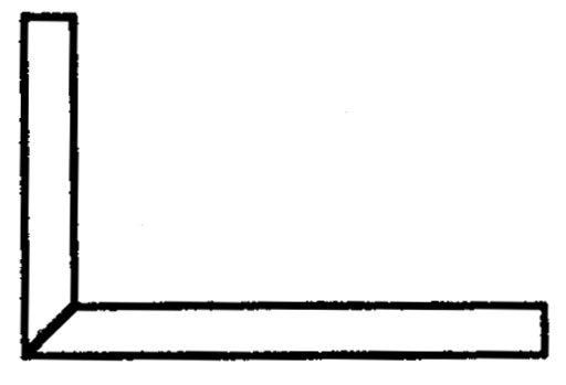
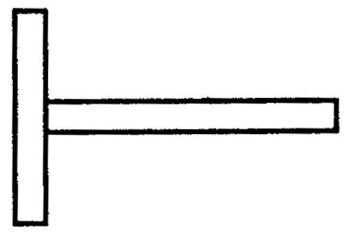
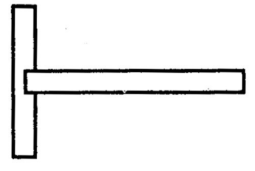
The bridge truss designs above show three variations based on the King Post type. The idea is to distribute the load across several member supports, that way all the load is not concentrated on one part of the beam, i.e. the beam does not take all the compression and tension. The first illustration shows one beam, but the second one shows three member supports, therefor spreading the load even more. To strengthen even more, instead of straight member supports, using triangles such as in illustration 3, the bridge is even stronger.
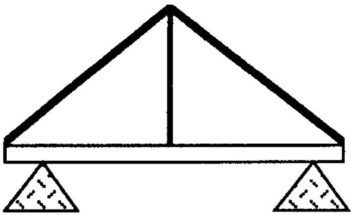
Simple Truss
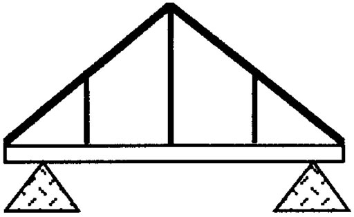
Adding Members
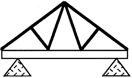
Triangulation
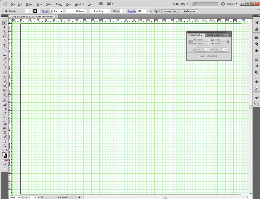
Illustrator
Illustrator is a vector drawing program that allows you to draw shapes quickly and accurately. By drawing your designs in full scale orthographic views, will allow you to use those views as your printed blueprint drawing for making your bridge components. Before you can do this you will need to practice making a simple truss using Illustrator to get familiar with it's drawing tools and process.
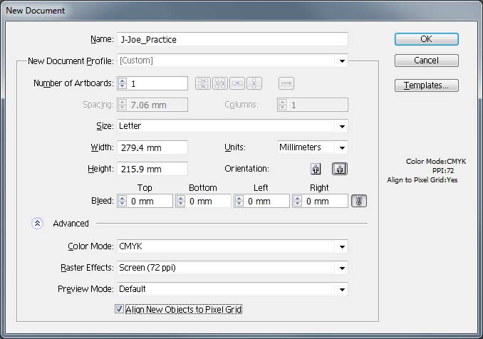
- Open Illustrator and select New File with the following settings
- Fill in appropriate file name
- Print for profile document type
- mm for units
- Landscape orientation
- Advanced and pick 72 dpi for raster effects
- Click OK
- Next pick a few general page options:
- View >Rulers > Show rulers
- Edit > Preferences > Guide and Grids, set grid to 5 mm
- View > Show Grid
- Press Shift F8 (for object information box)
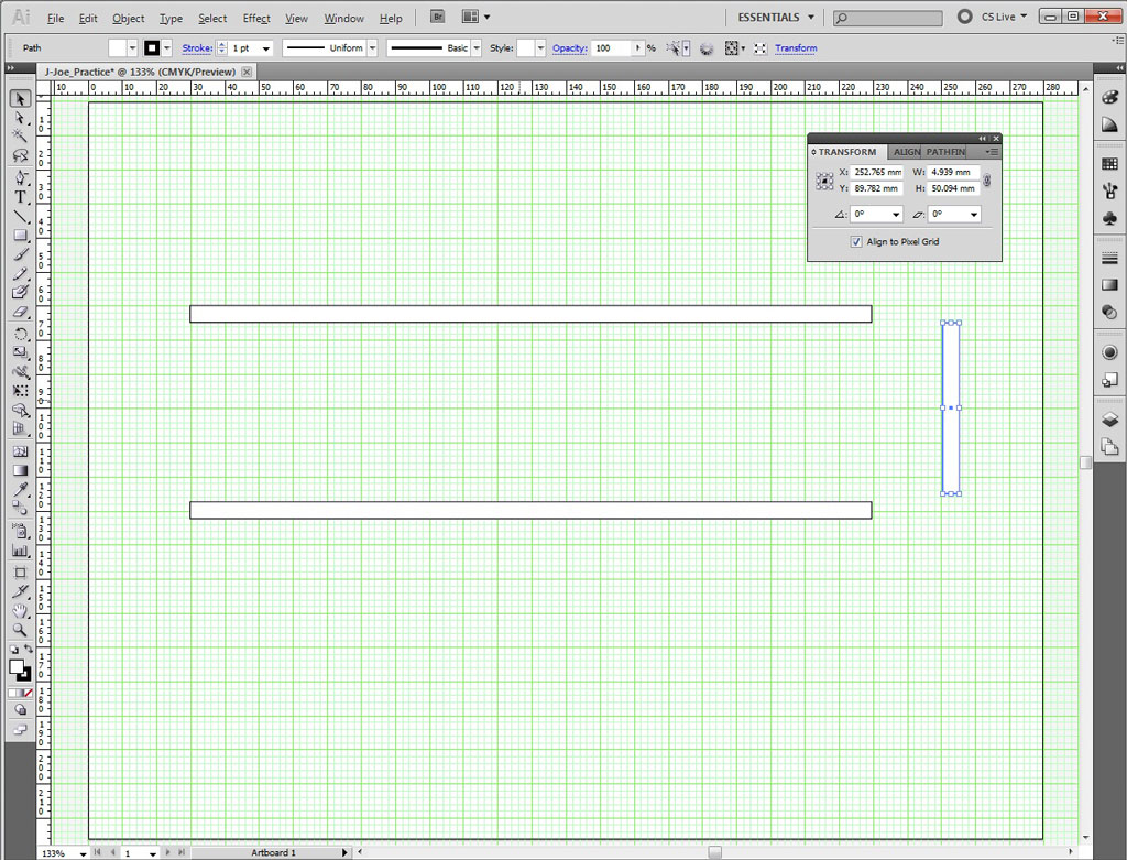
- Make two bridge beams and a support
- Select Rectangle tool (m) and left click on art board, put in 200mm for width and 5 mm for height
- Select the selection tool (v) and select beam on art board, then ctrl C to copy, then ctrl F to paste on top, then click and drag beam down so there are two parallel to each other
- Select Rectangle tool (m) and left click on art board, put in 5mm for width and 50 mm for height to make a support member
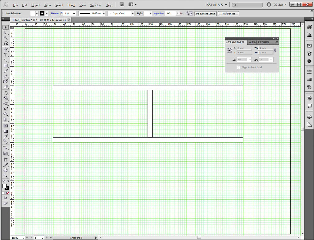
- Use Selection tool (v) to move the support member in between both beams in the center
- select and move bottom beam so that it touches bottom of support member
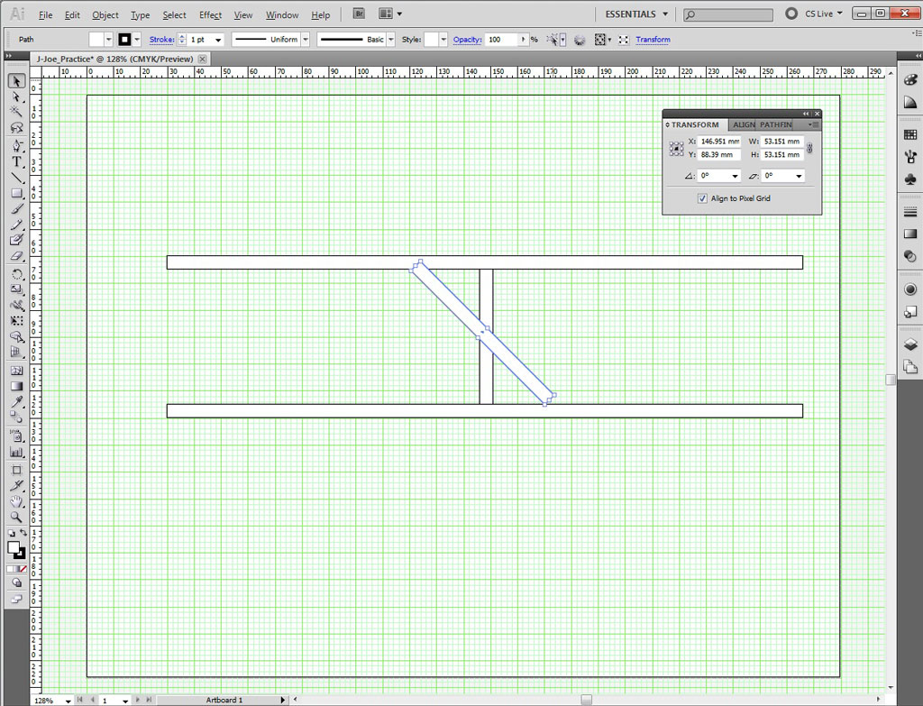
- Make a simple truss using rotate tool:
- Use Selection tool (v) and select the middle support member and ctrl C to copy, ctrl F to paste on top
- In the object information box, select 45 degrees in the rotate box, then select middle anchor top and pull to top beam, do the same for the bottom
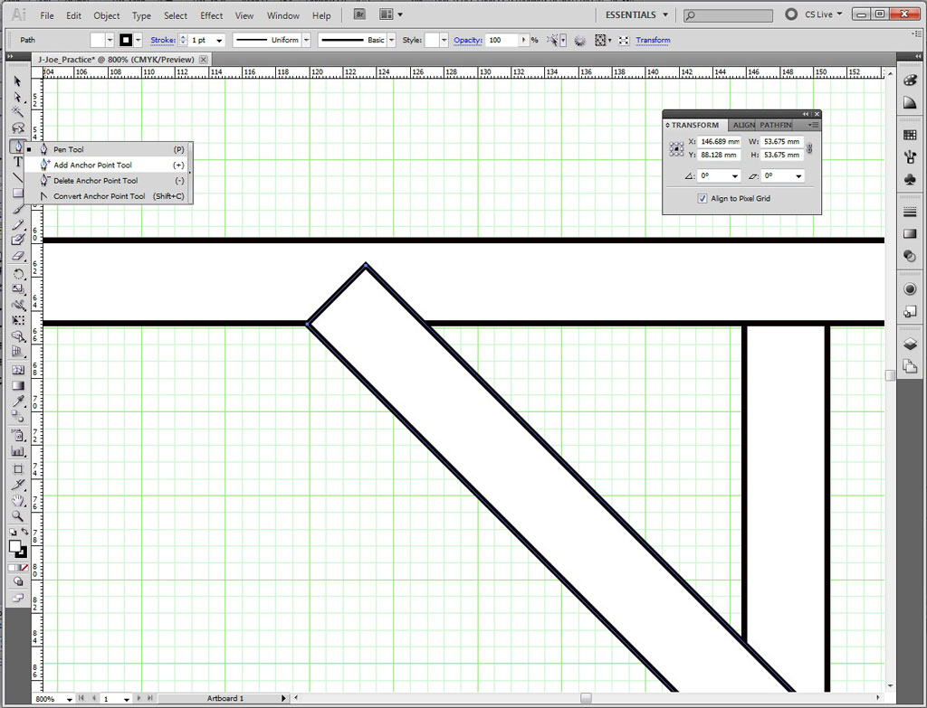
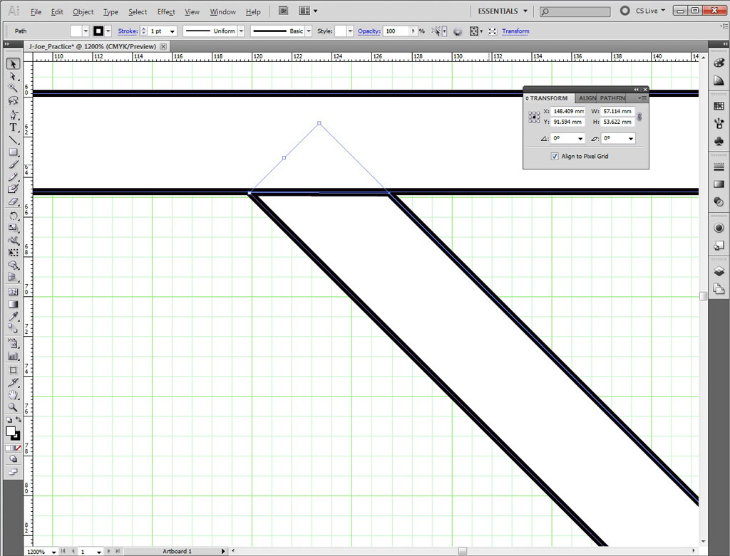
- Zoom in rolling the middle mouse button and pressing the alt button at the same time to view the top intersection of 45 degree support member and top beam
- Click and hold the pen tool fly out, select add anchor, then add an anchor point where the beam intersects the support member
- Click and hold the pen tool fly out, select subtract anchor, then delete anchor point(s) above beam line
- Do the same for the bottom of the support beam, then move 45 degree support member to the left
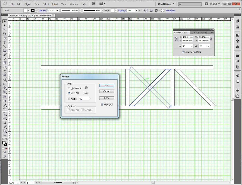
- select both the straight original support beam and the 45 degree beam, ctrl C, ctrl V, then move copy beside on the right
- Using the selection tool (v) right click on a 45 degree beam, select Transform > Reflect
- In the Reflect window, select vertical, select preview, then copy
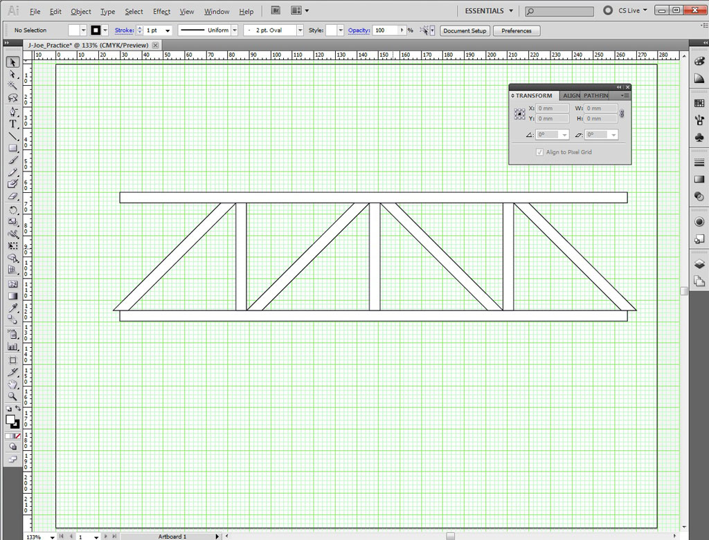
- Finish by adjusting the length of the top and bottom beams, using the selection tool (V), click and drag middle anchor of beams
Step 3a-c
Step 3d-e

Step 4a
Step 4b
Step 4c-d
Step 4e
Step 4h
Step 4i

Step 4j
Here are some support links explaining more about Illustrator:
Create/Construct:
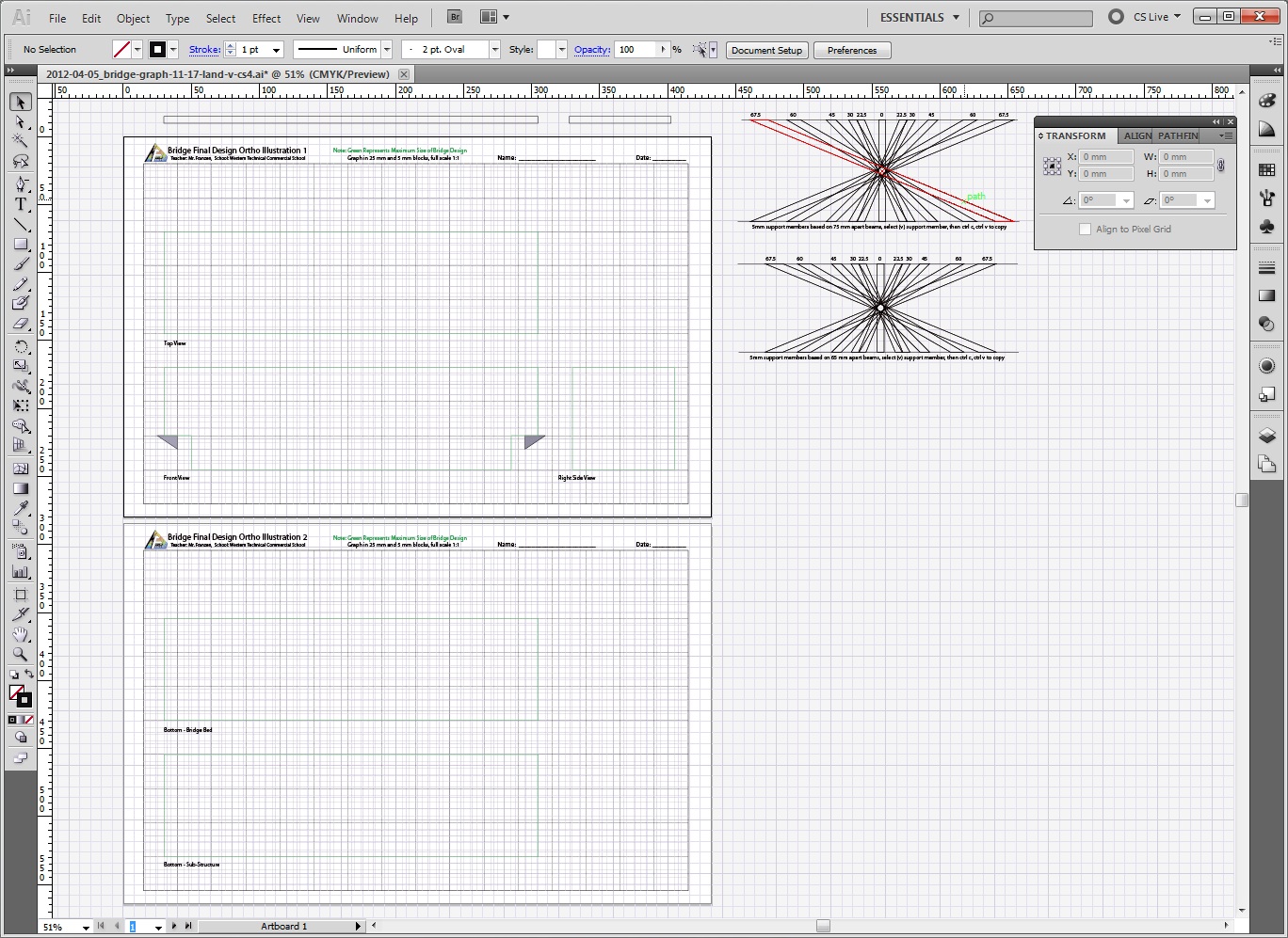
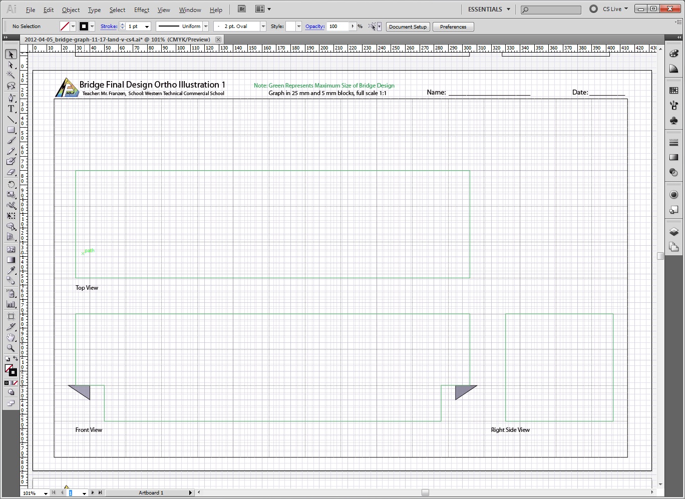
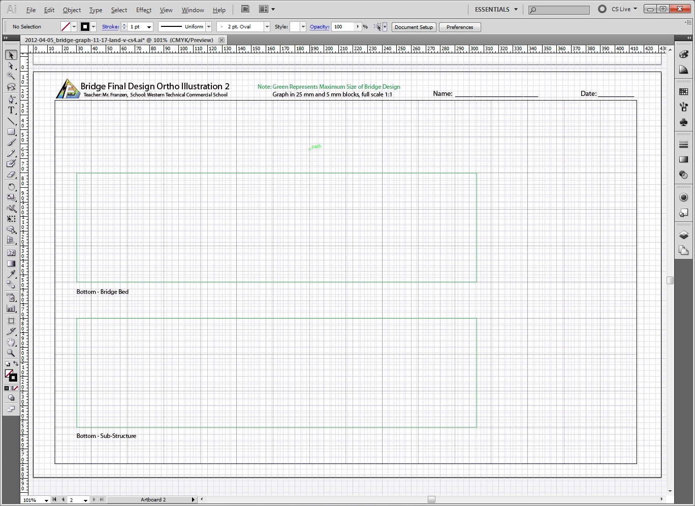
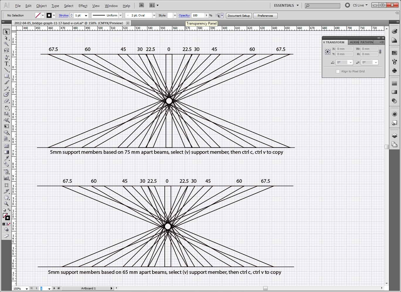
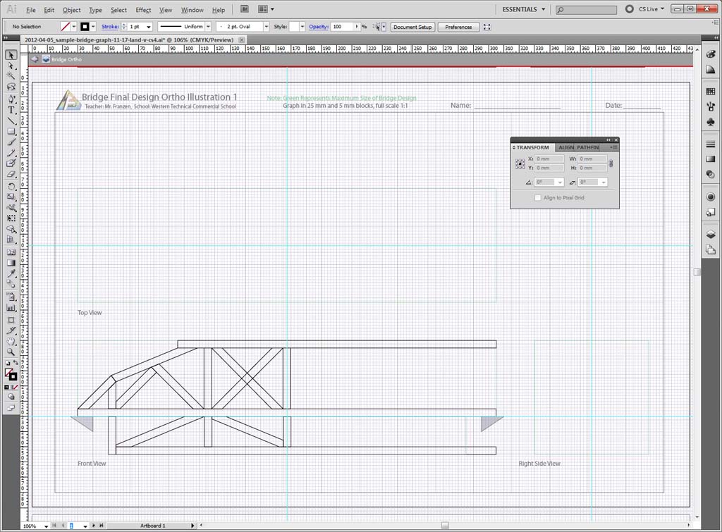
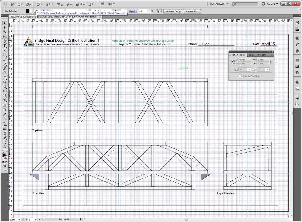
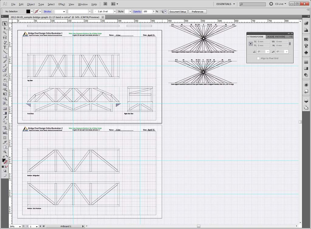
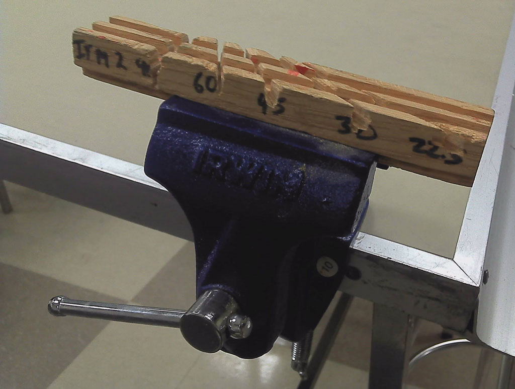
Both you and your partner are to select your final bridge designs and draw them accurately in Illustrator using supplied template found in the school pick-up folder. This is a 11 * 17, two page art board template giving you a 5 orthographic views, each outlining the maximum sizes you can draw. Views you will be able to draw are the front, top, side, bottom-road bed, and bottom sub-structure. You will find included in your template the following angled support beams both at 75 mm and 65 mm width's; 67.5, 60, 45, 30, 22.5 degree angles. Using the ctrl c and ctrl v will allow you to copy required support beams rather than have to make them.
Remember to save your work often and back-up to your H drive on your computer. You should be working off of your usb flash memory stick. Some last minute tips while working in Illustrator:
- Ctrl s to save quickly
- Ctrl 0 to zoom to all of the art board
- Alt roll centre mouse button to live zoom
- Space bar and left click to pan your work
- You can only undo your last mistake once ctrl z
- Use the direct selection icon tool to move individual points of a shape
- Use View > Outline to view just the line, view > preview to view regular view
- When moving a shape, after starting to move, press shift, and it will lock on the x or y axis as you move the shape
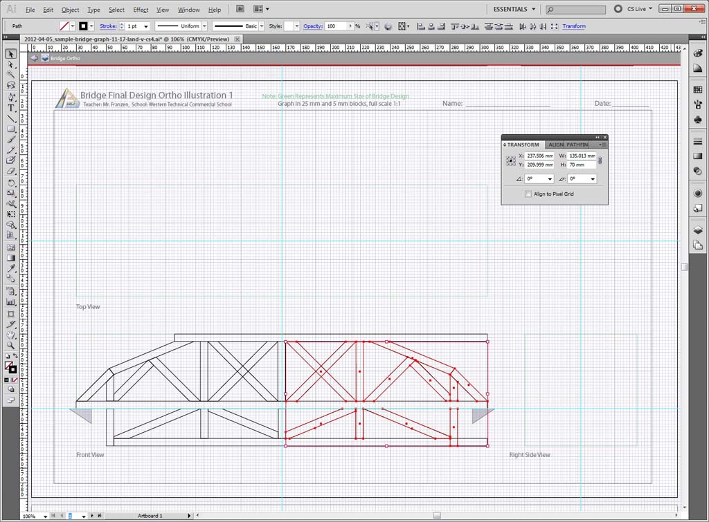
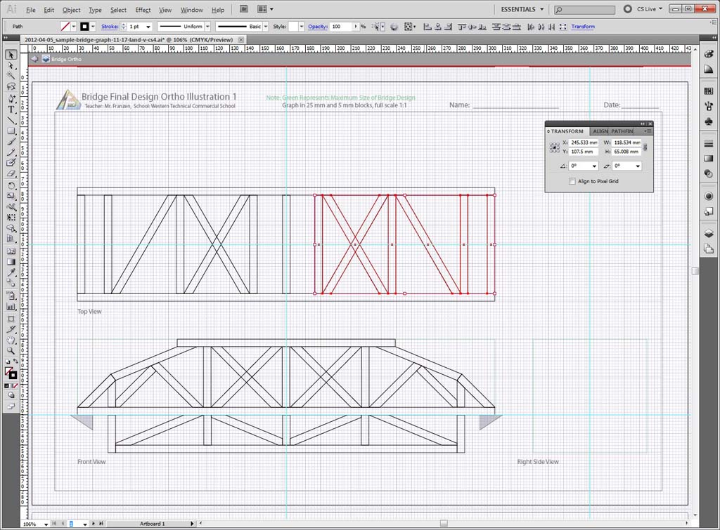
- Most importantly,right click on several components, use Transform >Reflect whenever possible to copy symmetrical bridge components
Below are samples of a finished bridge roughed in using the template and the above tips. Note the Sample Final B and C shows the reflected red outline of bridge components that were reflected. This will save you a lot of time if you can do this when possible. Make sure you put your name and date on both using the type tool icon.
Evaluation:
Have your teacher check your work once you are done, then copy to the respective hand-in folder in the school student share for later print. You will be using the printout to create your bridge components.

| Evaluation Breakdown Component Descriptions | Marks |
|---|---|
| Always double check that you have completed all components for full marks. | |
| Truss Tutorial - settings, beam and support member sizes and placement | 10 |
| Final Full Scale Drawing | |
| Design - well thought out, sizing, looks like it will work, TSA rules | 20 |
| Technical Drawing - beams and support shapes accurately drawn/placed | 10 |
| Orthographic Views - ortho views drawn correctly, and complete | 10 |
Unit 2, Act. 3: Building Efficiency
Situation:
Looking back we at the design process of this unit, we are all in the same situation with a class of students in an technical design class learning about technical challenges, coming up with researched information and new innovative ideas and how to communicate graphically your ideas. With lots of ideas and information, then deciding on the best idea to use, and then test the final idea... i.e. does the idea you used solve the problem. In our case it is to build the most efficient load bearing model bridge with the given materials.
Problem/Challenge:
At this stage of the unit, we are to safely build our final idea and then test it's strength. Finishing the final drawing in illustrator has given groups two final bridge design solutions. Your task, in your groups, is to decide on which of the two final ideas is going to be the most efficient bridge design to build, then build your bridge with the following limited amount of time, weight and materials supplied:
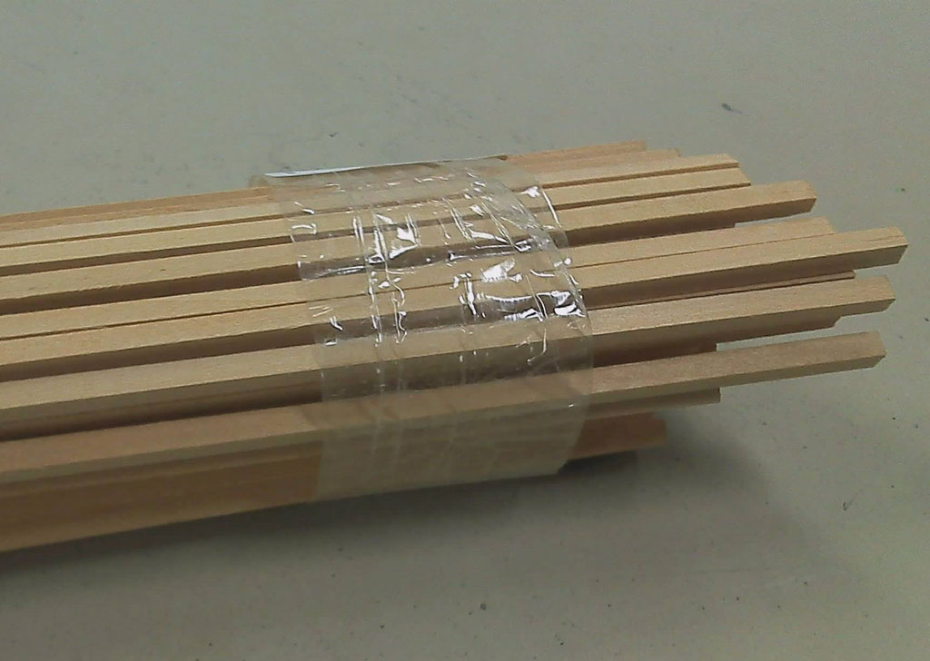
Bass Wood Strips
- full lengths of bass wood 5 * 5 mm
- 8 lengths at 610 mm each (approximately 9 grams each):
- 1 length at 380 mm
- Assorted small scrap pieces can also be used
- Paper gussets can be used
- Five periods or 1 full week prior to destructive testing
- Maximum of 150 grams for weight of bridge
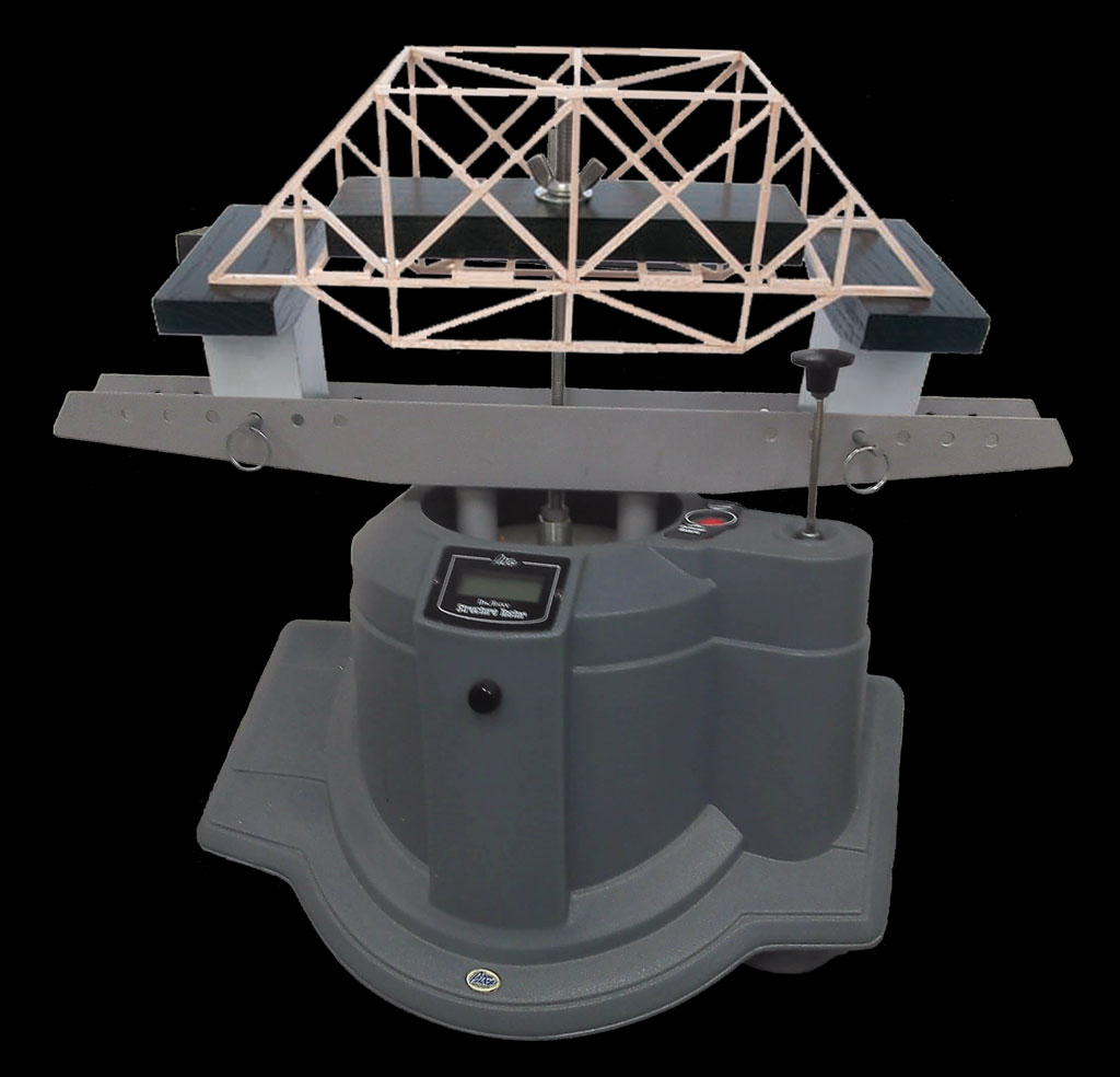
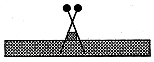
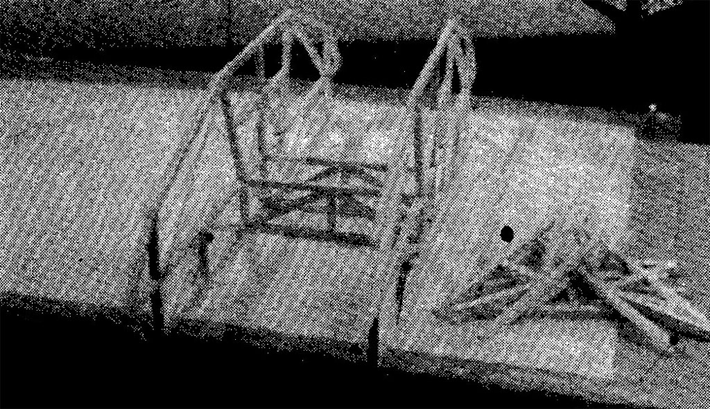
Once bridge is built, it will be destructively tested using a Pitsco Pneumatic Structure Tester (as show above). This tester is a pump action load weight bearing and load tracking, testing unit, which will apply weight and measure the bridge's ability to withstand the load. When the bridge does break under load, the final load weight that it was able to withstand will be indicated in the LCD readout. This value will be used to calculate the efficiency of your bridge. The higher the bridge efficiency the higher your mark will be, as your mark will be based on the average of all group bridge efficiencies tested.
Investigation/Ideas:
Below is a list of support resources you will be using with your bridge build. Each of the materials, tools, and equipment need to be taken care of. Ensure you have had instruction on all resources prior to using them:
Support Build Resources:
- 11*17 printed bridge design
- Large envelope for small pieces
- Secure storage area
- 11 * 17 corrugated cardboard
- Wax paper
- Wood glue
- Hand saw
- Hot Glue
- Mitre guide
- Mitre guide table clamp
- Mitre hand cutter
- Push pins
- Assorted elastics
- Office bimetal leverage clamps
- Electronic weight scale
- Flat fine file
- Sandpaper
- Masking tape
Images below show some of the resources we will be using. Note the glue gun is strictly just for gluing large bridge components such as the bridge sides to the road bed. Remember, you are not allowed to use any of the tools or equipment unless you have been specifically instructed to do so.
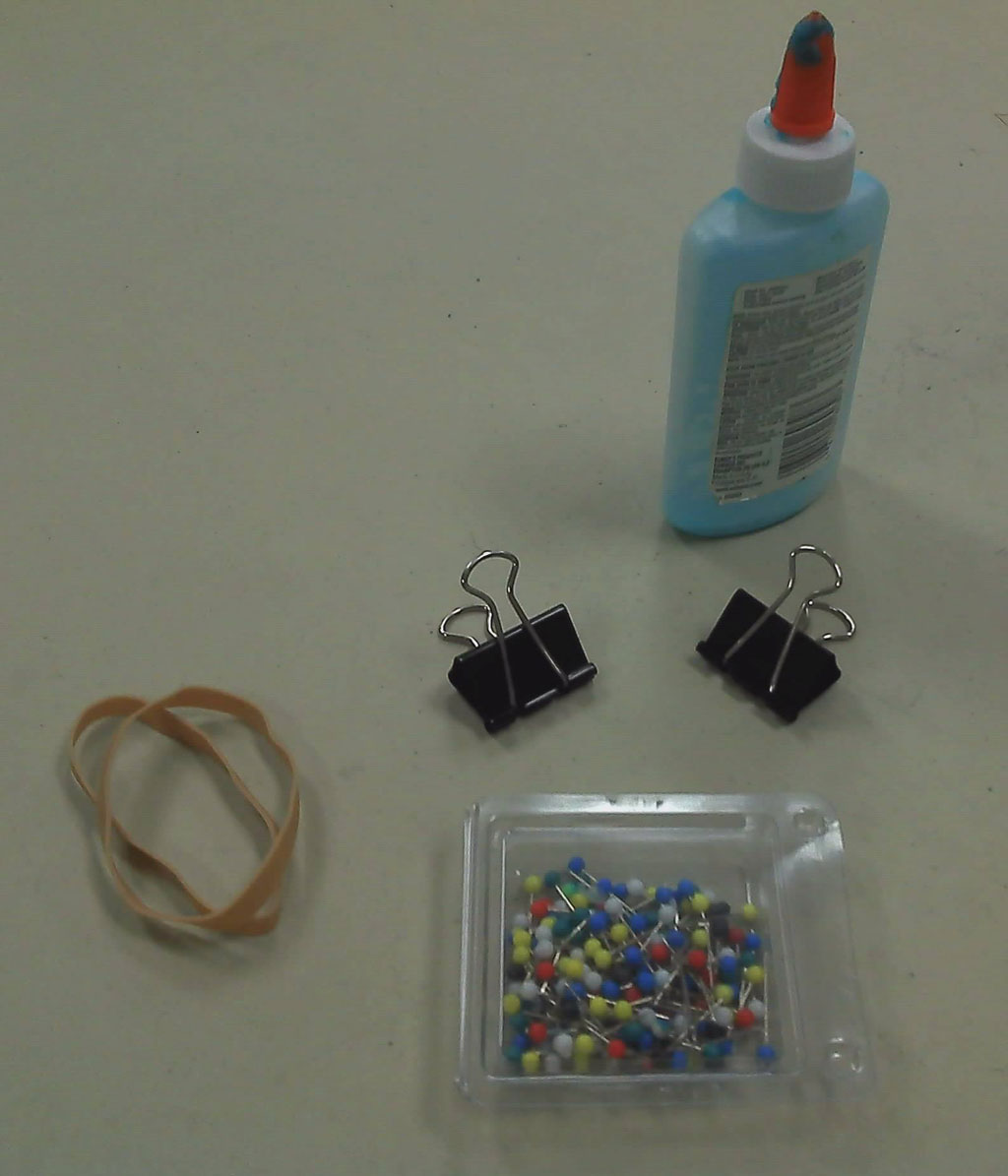
Assorted
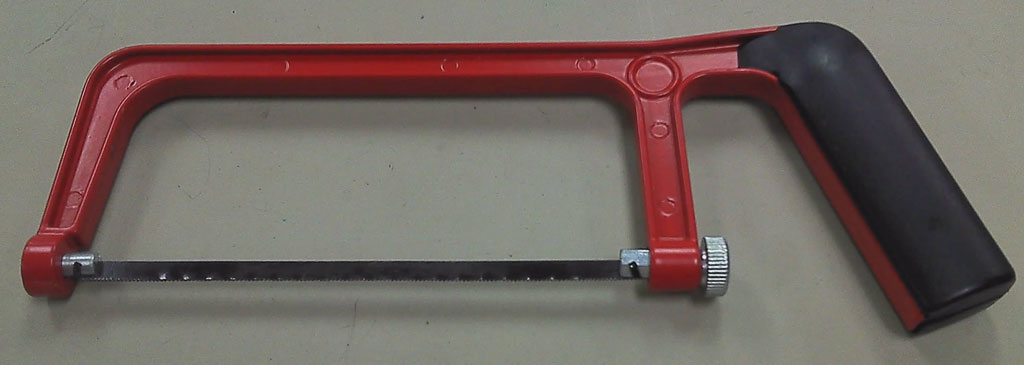
Wood Saw
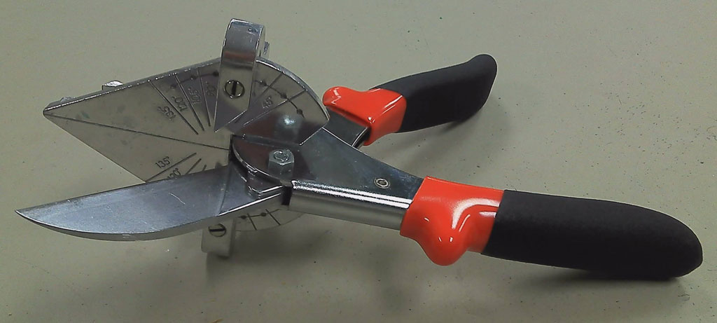
Wood Cutter
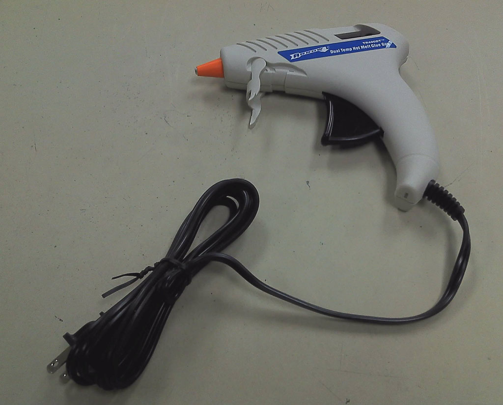
Hot glue
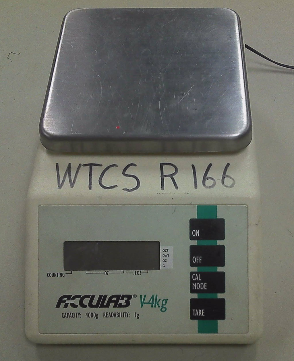
Weight scale
Mitre & Clamp

Wood Cutter
Wood Joints
Once you have established the best general bridge design, the next critical decision will be what kind of joints and how your pieces will be put together. One single weak joint can cause a chain reaction in your whole bridge collapsing, even if all your other joints are super strong. Try to utilize various joint types that are stronger then others for maximum support. Braced joints can be very difficult to make but, can provide an extremely strong joint.
Mitre
Butt
Notched
Half Notched
Joint
Cut Techniques
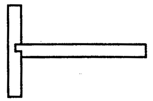
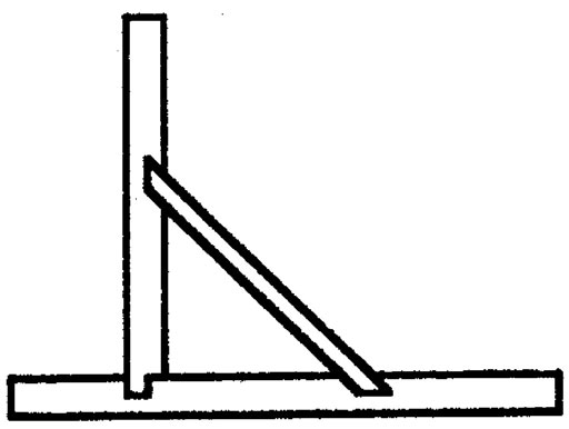
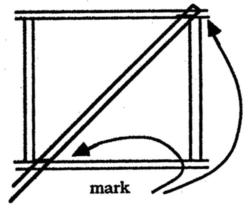
Cutting diagonal pieces, must be accurate and placed properly for maximum strength.
Layout
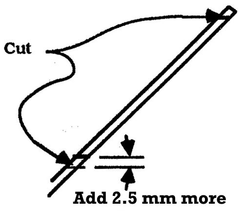
Cut 2.5 mm bigger
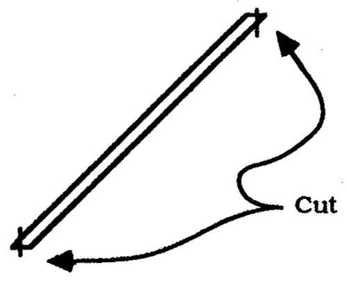
Cut other edges off
Glue into place
Pin Techniques
You will need a piece of 11 * 17 piece of corrugated cardboard, your drawing, and some wax paper. First tape your drawing to the corrugated cardboard, then place your wax paper over top of your bridge drawing and tape it down also. Use the push-pins as shown below.
2 pins hold wood
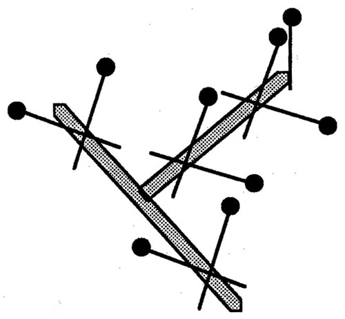
Multiple pins used
Create/Construct:
General steps you will be following:

- Tape your final bridge drawing on to the corrugated cardboard
- Place wax paper over top of your drawing and tape on edges
- Start by cutting out largest outside pieces of the side of your bridge
- Use pins to secure in place
- White glue all outside pieces
- Cut all side of bridge support pieces and pin into place
- White glue all support pieces
- Do the same for the other bridge side
- Cut cross-sectional pieces for top and bottom of bridge
- White glue all cross-section pieces together, and let dry
- Use hot glue to fit together ends
- White glue all other cross-sections and use clamps elastics etc
- Extra glue for poor/loose joints will not make them stronger
- Not a lot of glue is needed for each joint
- Minimum 12 hours for all glue to dry, prior to testing
- Bridge will be tested under an increasing load
- Record the "Failure Weight" to be used in Efficiency calculation
- Fill in Bridge Evaluation report and include feedback
Cut and Glue Process
Cut your largest outside pieces first, then place the pieces on the appropriate location. Use the push-pins to keep parts in place. As you cut your pieces pin them into place on the corrugated cardboard. Save your gluing until you have all your pieces cut, to make sure everything fits.
Start side profile- largest pieces first
Finished with smaller pieces
Fitting Together Cross Sections
Create your cross sections that will connect the two side rail beams
Sections
Fitting Cross Sections
Completed bridge
Model Bridge Samples
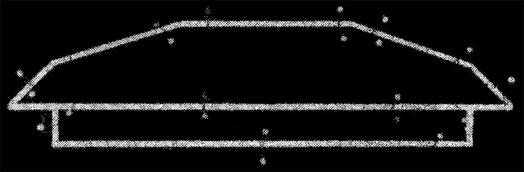
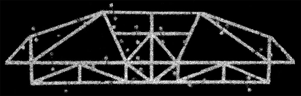
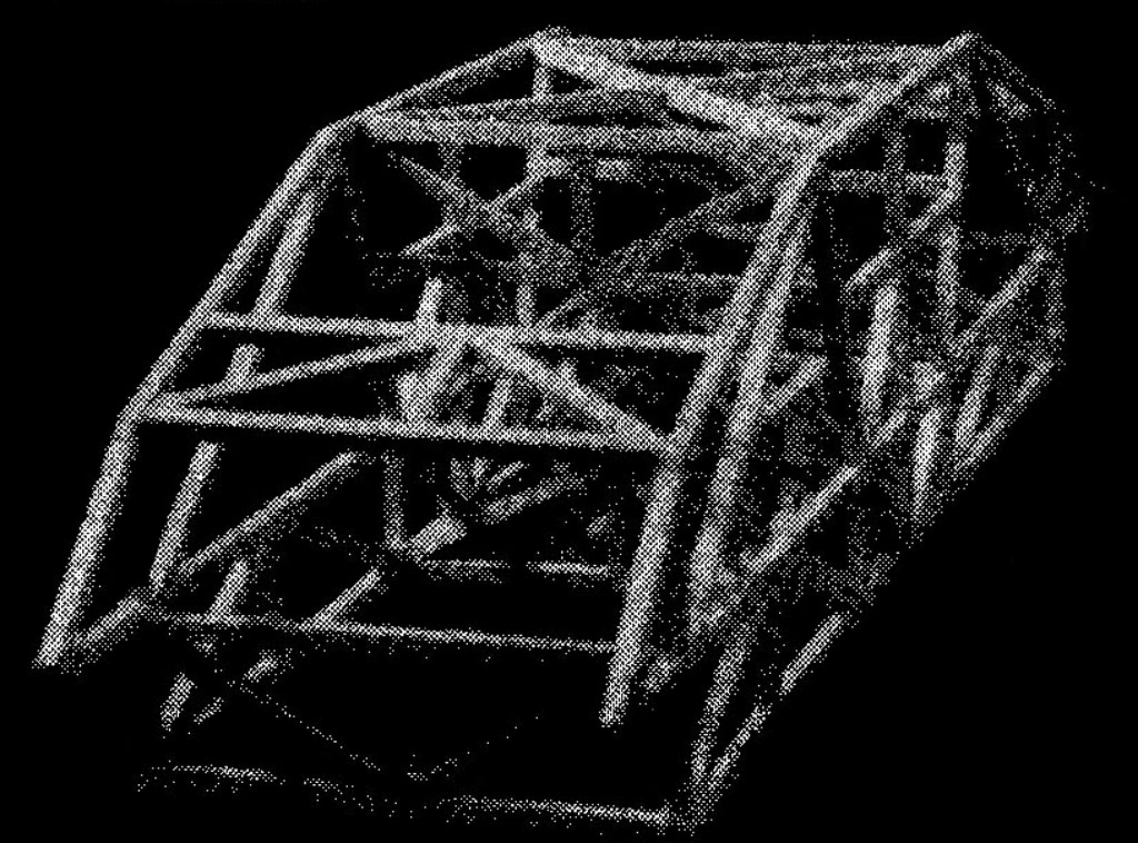
Here are some sample images of different bridge models, note triangulation used on all samples. Look closely in the third sample and note how the floor bed has been created... on top of beams:
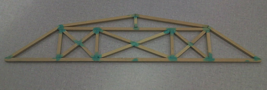
Super Structure Side
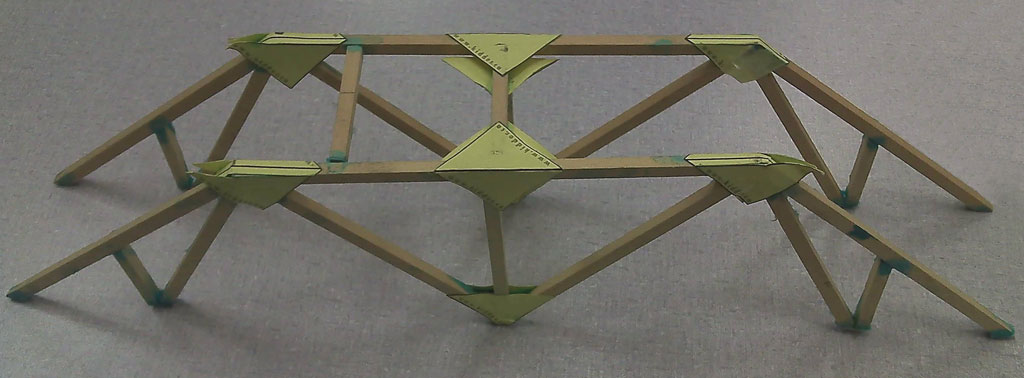
Super Structure Top
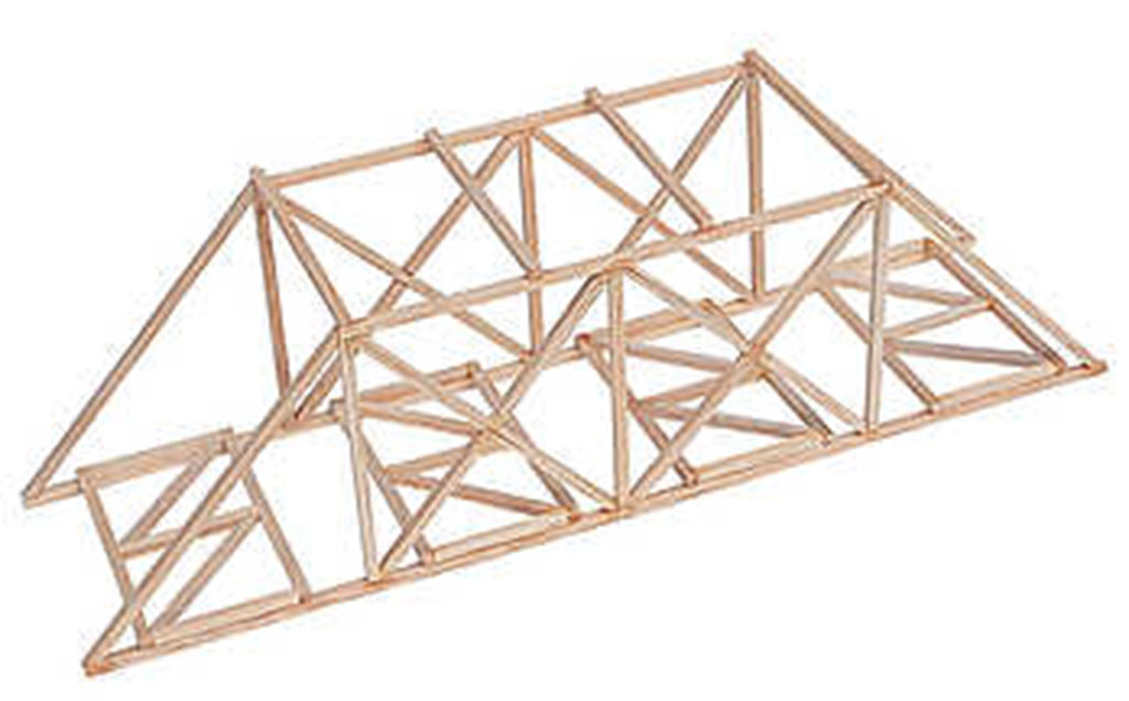
Full Bridge Model
Evaluation:
Ensure you fill out your Bridge Evaluation![]() report properly. Make sure you take the time to build a quality bridge as the bridge is only as strong as it's weakest point.
report properly. Make sure you take the time to build a quality bridge as the bridge is only as strong as it's weakest point.

| Evaluation Breakdown Component Descriptions | Marks |
|---|---|
| Always double check that you have completed all components for full marks. | |
| Specifications - correct sizes, weight, centre space for block | 20 |
| Wood Joints - tight, little glue, triangulation, strong support | 20 |
| Efficiency - weight of load / wight of bridge | 20 |
| Craftsmanship - well put together and parts not twisted | 20 |
| Bridge Evaluation Report - Filled in accurately with good explanations and new sketch | 20 |