Unit 7: Grade 11/12 Technological Design - Robotics - Marketing Portfolio and Design Log
With Technological Design and Engineering, one key element is showcasing your work by building a portfolio and design log. For this course you have had the opportunity to learn about the design process using SPICE as a model and applied common steps to all projects. To define and showcase steps in a medium that is easy to organize and share, a word document is a great way to do this and show your accomplished work, learning, and steps taken,when creating a portfolio.
Unit Content Activity Quick Links, Click to Jump to Specific Activity!
 Unit 2, Act. 2: Applying the Design Process
Situation:
A class of students interested in the field of Engineering have taken a course to find out what Technology Design is all about. One of the major principals of this course/field is the "Design Process". Coming up with solutions is what Engineers do on a daily bases.
Problem/Challenge:
This is a two part project, with the first part understanding the design process and identifying the steps on different tasks/challenges such as coming up with an idea for a Key chain accessory using this process. Your task is to use the design process model, SPICE to design a practical/decorative key chain accessory to be later drawn in CAD and printed in 3D using our 3D printer. While doing this you are to also identify and report on the design steps in relation to this project to show your understanding of SPICE. The key chain accessory is to include:
- A design that is unique, custom, practical/decorative and related to tech
- Equivalently sized to approximately the size of a chap stick container
- A minimum 5 mm diameter hole for the key ring with at least mm sufficient support material around the hole
- A minimum 5 mm general thickness
You will need to show the following when going through the process of this project:
- The first three steps of SPICE explained in terms of this project the key chain accessory
- Five different thumbnail ideas and labeled
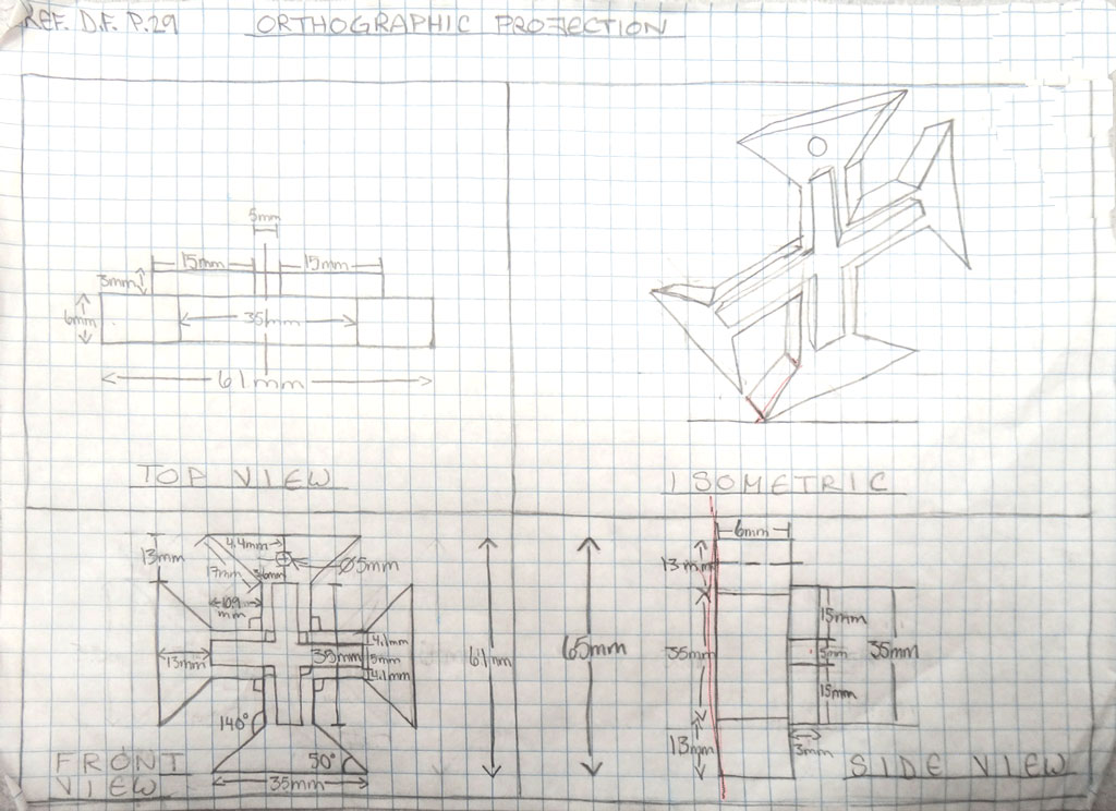
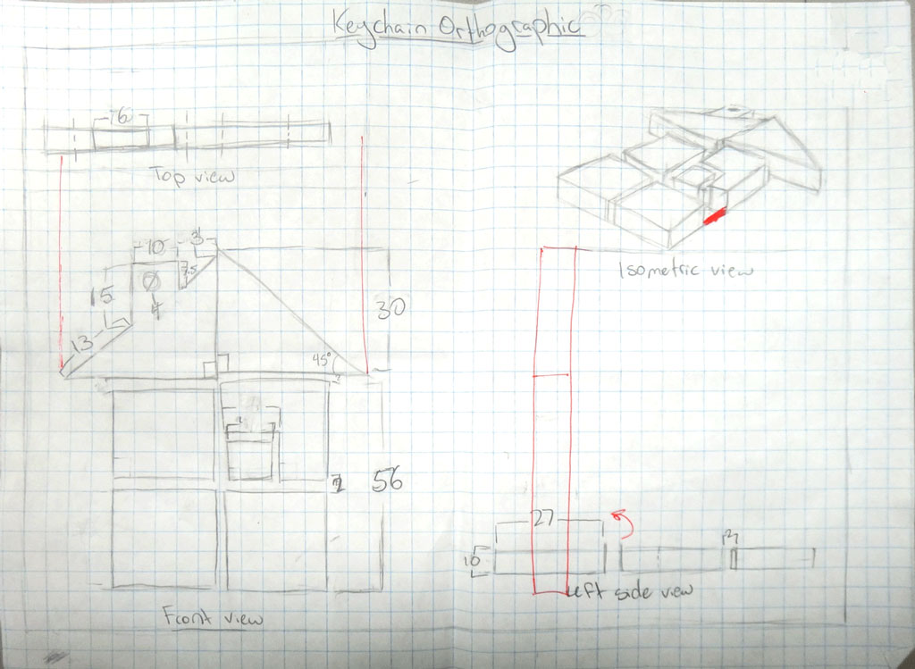
- Final full page scaled orthographic sketch showing all needed dimensions and an isometric view

For those that would like to customize their own idea, they will require a ![]() proposal Word form to be filled out and approved by the instructor which you can get from the school pick-up folder. The idea must still follow the same process of current project but may have a different product.
proposal Word form to be filled out and approved by the instructor which you can get from the school pick-up folder. The idea must still follow the same process of current project but may have a different product.

Investigation/Ideas:
A design process is what engineers, antipersonnel, inventors, etc. use or go through to come up with great solutions to resolve or find solutions to problems. There are many design process models out there, some very long and detailed wile others simple and short. Most successful corporations will already have a process that employees must follow while working which involves reporting on those steps taken. We will look at some of these models and focus in on one specifically called SPICE to show how the technical design process works and also below are some more support links on thumbnail sketching:
- SPICE Design Process Model (We will be using this model)
- A detailed look on each stage of designing
 Six Models of the Design Process
- Thumbnail sketching - some samples
- Thumbnail Sketching in a design process- a detailed look
 Freehand sketching to develop the idea and plan 3D modeling
Samples of Work
The following samples show what thumbnails would look like and how your orthographic sketches would look like when applied to other designs such as key ring accessory project.
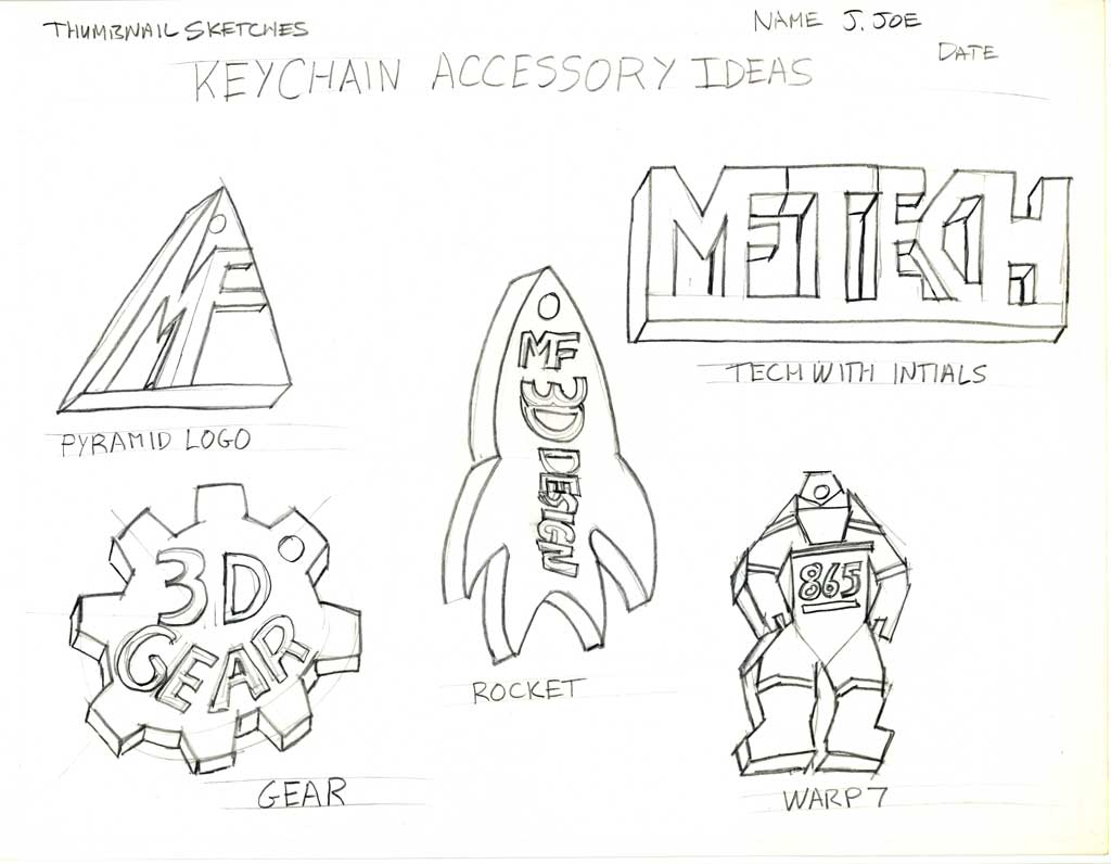
Thumbnails
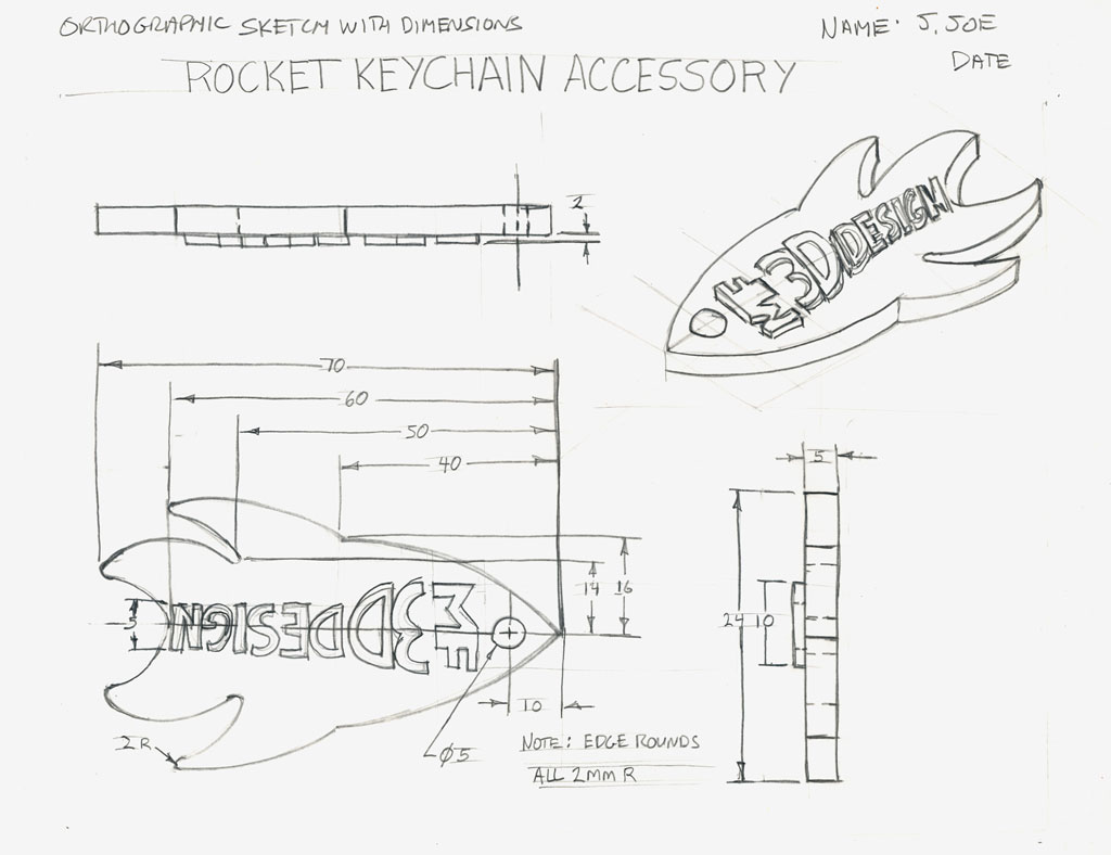
Ortho 1
Ortho 2-3D CAD
Ortho 3 - 3D Print
Robot Design Process
Interestingly enough, this simple project will gain you some key knowledge about design process and steps that you can apply to just about anything, including the design and building of robots. As this is the focus of this course the next unit will start looking at a specific FIRST robot challenge and going through the design steps by example to come up with a working solution. With this experience, you will have an opportunity to apply it to your own custom robot design, allowing you to repeat and practice what you have learned, allowing you to also refine and enrich details about this process.
Create/Construct:

So this is the section called Create/Construct, which if you have understood the SPICE design model process from the investigation/ideas section, is the part of the process where you select your best idea and act upon it to accomplish your goal (problem/challenge). With these activities I use this section to give you the steps you need to take to accomplish what we need to do in class to learn and experience through hands-on activity such as below:
Design Process Steps Reported and Applied to a Key holder Design
- On a sheet of paper write down the following topic/headings:
- Situation
- Problem/Challenge
- Investigation/Ideas
- Each topic/heading is to have two to three lines of information explaining what that SPICE step is in relation to the the task of making a key accessory
- The Investigation/ideas will include what your ideas are maybe some research and also include the five thumbnails showing your key accessory ideas
- Once you have completed your investigation and have many ideas, you will select your best idea and...
- Draw a scaled (i.e. to fill the page) orthographic showing correct front, top, and right side view similar to the ortho 1 sample above (ortho 2 and 3 are samples of what junior grades have accomplished) with dimensions and an isometric
Evaluation:
You will be evaluated based on your SPI key accessory explanation, thumbnails, and final orthographic design.

| Evaluation Breakdown Component Descriptions | Marks |
|---|---|
| Always double check that you have completed all components for full marks. | |
| SPICE - SPI part of the design process of the key accessory | 10 |
| Thumbnails - create five thumbnails filling a full page with notes on key accessory | 10 |
| Orthographic - sketch showing final design with 3 views, dimensions, and isometric | 20 |
Unit 2, Act. 3: Basic 2D Drawing Using DraftSight

Situation:
Having now learned about sketching, orthographic and isometric drawings, it is easy for you to communicate effectively with pencil and paper throughout the technology design process. With the advancement of computers and software applications, it has helped people today get things done faster, more efficient, and more organized. It has also saved on the environment in many ways including paper saving. Drawing programs have come a long way in the last 15 years and it is a great way to not only communicate, but also modify and update your ideas very easily.
Problem/Challenge:
Using the recent orthographic sketch of the step block , redraw using absolute and relative coordinate systems to draw the three views spaced apart 40 mm, isometric view, hidden and centre lines, dimensions, and use of layers for drawing colour, line types, and control of drawing components. Linked sheet is to be used with it's view port scaled to show drawing model and fill-in information block details to hand in the program's proprietary file format, dwg and export also as a pdf.
Advanced Challenge
If you have already experienced 2D CAD working with the input coordinates command line system, then your challenge will be to select another ortho sketch challenge and with same challenge requirements, process steps of the step block, and the template, create/complete a 2D drawing model with the correct front view and detailed isometric view with appropriate layers, lines, weights, dimensioning, spacing, scaling, sheet view, info block saved in dwg and pdf file format submissions.

Investigation/Ideas:
DraftSight is a 2D drawing program that can accurately draw objects using simple commands- video ![]() Introduction. This type of program is commonly used in a variety of fields where layout drawing plans are needed to communicate a lot of information graphically. Drawings use the Cartesian coordinate system and there are two major ways to enter lines, either absolute or relative coordinates. Simply put absolute coordinate system uses point entry method based on a single starting point or origin, where the relative point entry method you enter coordinates based on your last coordinate location. More details on command entry which also talks about the type of coordinate system you can enter in such as Cartesian (2D / 3D), polar (2D), cylindrical (3D), spherical (3D) with Cartesian and polar most often used. Before starting to draw your step block, explore the program, experiment with different tools and familiarize yourself with the applications interface, as it is similar to other CAD programs used in industry. The DraftSight Resource Centre has lots of support files you can view including videos showing the basic steps.
Introduction. This type of program is commonly used in a variety of fields where layout drawing plans are needed to communicate a lot of information graphically. Drawings use the Cartesian coordinate system and there are two major ways to enter lines, either absolute or relative coordinates. Simply put absolute coordinate system uses point entry method based on a single starting point or origin, where the relative point entry method you enter coordinates based on your last coordinate location. More details on command entry which also talks about the type of coordinate system you can enter in such as Cartesian (2D / 3D), polar (2D), cylindrical (3D), spherical (3D) with Cartesian and polar most often used. Before starting to draw your step block, explore the program, experiment with different tools and familiarize yourself with the applications interface, as it is similar to other CAD programs used in industry. The DraftSight Resource Centre has lots of support files you can view including videos showing the basic steps.
DraftSight Support links
You can download a in-depth guide to ![]() Getting Started if you want more information on the operation, tools, and interface. A quick
Getting Started if you want more information on the operation, tools, and interface. A quick ![]() DraftSight video introduction can show you the basics,
DraftSight video introduction can show you the basics, ![]() playlist of specific tools,
playlist of specific tools, ![]() playlist of lessons, and/or view a longer version of
playlist of lessons, and/or view a longer version of ![]() DraftSight Fundamentals webinar showing the program in more detail.. DraftSight is free to download and use at home to not only work on related school work but also for your own projects. Remember while working, save your work to your USB flash drive and always backup to your H drive at school or if you are working at home backup to your home computer.
DraftSight Fundamentals webinar showing the program in more detail.. DraftSight is free to download and use at home to not only work on related school work but also for your own projects. Remember while working, save your work to your USB flash drive and always backup to your H drive at school or if you are working at home backup to your home computer.
DraftSight Tips/Tricks and Key Information

- General settings go to Tools, and select Options to access all the general settings for the program
- Background colour using Options, System Options, Display, select Model background, then change colour to white, although the default black will work fine
- General set-up Limits CMD (Command) sets your model workspace area, Units to change decimal place holder and units, & grid spacing
- Z for zoom, then letter for type of zoom such as E for extents, A for all objects, etc.
- Absolute coordinates allows you to enter location based on the origin point in relation to where you want to draw or locate a element
- Relative coordinate entry allows you to enter a location based on last location
- When drawing lines, having Ortho on, you can save some time drawing lines that are straight horizontal or vertical by using the cursor to show direction, then just enter in the distance and press enter to draw that line
- "From" CMD will allow you to offset your starting point location of a line or object
- E-snap allows you to quickly lock onto common feature points of lines or shapes
- E-track will allow you to align a edge or e-snap point to another view or drawing location
- Use layer manager to create new layers to manage different parts of your drawing like object, text, dimensions, notes, special views, etc and control colour, view, line thickness, line type, layer, scale, locking etc.
- Most likely will need to scale dimension lines, arrows, text, special lines, etc, doing so with a selected component will only change what is selected, or with no selection will change everything on that layer
- Using note tool will allow you to make notations
- Using dimension commands you can enter dimensions on a newly created layer
- Adding new specialized lines, you may need to load them from the library to attach to layers
- Line weights in model space are shown by going to Format, Line weight, check off Line weights in graphics area
- Line weight issues in sheet view, enter the CMD ENBLVPLSCL and set default from 1 to 0, then enter CMD Region
DraftSight ISO Drawing View
- Creating an Isometric Drawing with DraftSight
- Adjust cursor - Options, Graphic Area, select cross hair with pointer size increased %100
- ISO Grid - right click on Grid button, Settings, Grid settings - select isometric
- Three separate planes- left, top, and right - toggle through using F5, command window will tell you where you are
- Put ortho on
- Using line tool create your ISO
- Use ellipse tool to access isocircle option to draw circular holes on ISO planes, you may need to use temporary construction lines to find centres
Create/Construct:
Using the 2D CAD program called DraftSight, create an ortho of the step block as in our final sketch in the past unit, using the following brief steps used from the live demonstration from the instructor.:
Unit 3, Act. 4: Basic 3D Drawing Using Google SketchUp Make
Situation:
Learning to draw and design with different technical drawing programs is a great way to communicate your ideas accurately and can easily be modified to future needs. As a technical design student this can be a very helpful tool with the design process.
Problem/Challenge:
You are to accurately draw the step block we sketched in class and in the previous application DraftSight. Dimensions are also to be added in a neat organized manner showing all overall dimensions and detail dimensions. Finished file to be handed in with the proprietary file format extension and also as a jpg.
Advanced Challenge
If you have already experienced basic 3D Sketchup working with basic push/pull tools and dimensioning, then you know the challenge will be to select another ortho sketch challenge from our earlier custom sketch project to create your advanced object with dimensions similar to step block sample.

Investigation/Ideas:
Google Sketchup is a free program and has a lot of support on the Internet including forums, part database, and tutorials. This program is closely used with Google Earth to build and show 3D buildings on it's maps. This program application has many setup configurations to allow different types of drawings and standards. The drawing tools represent simple tools and icons for drawing and push/pull shapes into 3D. This program can be used to draw simple or complex objects very easily. Review your dimension rules and standards and how to keep them to a minimum but also ensure you have enough to re-create it if needed.
Extra help/resources can be found here if you need more information. Many more resources can be found online showing different methods to draw objects. This is a free program you can download here and install on your system. Further resource links can be found here:
- How to Create Your First 3D Model in SketchUp
- How to Use SketchUp
- Sketchup Tutorials for Any Skill Level
- SketchUp tutorials
- SketchUp Tutorial for 3D Printing Beginners
- Official Google SketchUp You Tube channel.
- Learn SketchUp
- Video Tutorials: Getting Started
Create/Construct:
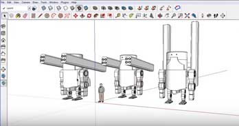
Here is a list of the major steps that were show during the class demonstration, and a final 3D drawing sample that you can follow if you need extra support:
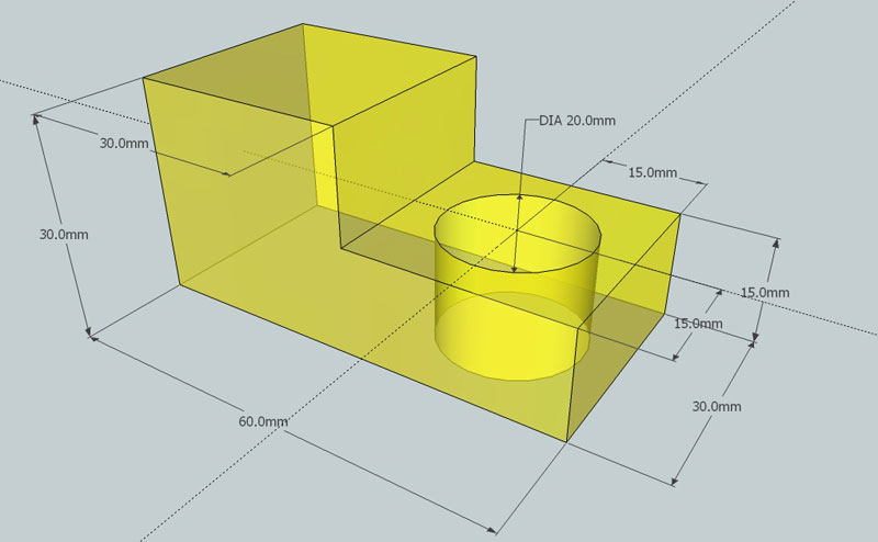
Sample 3D Step Block
- Select template: Product Design and Woodworking Millimeters
- Draw a rectangle using the Rectangle tool, type the exact height, press enter
- Use the zoom extents icon to re-size, re-draw and center your object at any time
- Use the push/pull tool to pull up the object up, type the exact height, press enter
- Finish the rest of the block using the same tools/process
- Tip: use the tape measure to find centre for hole.
- Create/show dimensions by selecting the menu tools, and dimensioning
- Show overall and detail dimensions
- Use the colour tool to create a transparent colour
- Save in proper file format in two file types: SKP and JPG formats
- Use File > Export > 2D Graphics for creating the JPG (ensure image/dimensions are taking up most of the page
- Tip: ensure view is centred and full screen prior to exporting to JPG
When you are finished check with two peers to ensure you have completed the tutorial correctly.
![]() When handing in any files, you will submit in the Drop-Off folder as discussed in class, in the proprietary program file format extension SKP and also export to a jpg format. Ensure the file extension is correct and present. Here are some examples of file name you should be using:
When handing in any files, you will submit in the Drop-Off folder as discussed in class, in the proprietary program file format extension SKP and also export to a jpg format. Ensure the file extension is correct and present. Here are some examples of file name you should be using:
- Google Sketchup file name example: tdj_3dstepblock_d-joe.skp
- JPG - Joint Photographic Experts Group file name example: tdj_3dstepblock_d-joe.jpg
Evaluation:

The chart below breaks down this project into three areas, object, dimensions, and final drawing. Make sure you hand in your work in the two formats shown above.
| Evaluation Breakdown Component Descriptions | Marks |
|---|---|
| Always double check that you have completed all components for full marks. | |
| 3D Object - file set-up, object size, and features correctly drawn | 10 |
| Dimensions - all overall and necessary detail dimensions neatly located | 5 |
| Final drawing - colour fill, lines, overall look, saved in SKP and JPG formats | 5 |