Unit 7: Grade 10 Technological Design -
Robotics - Web Portfolio
With Technological Design and Engineering, one key element is showcasing your work by building a portfolio. For this course you have had the opportunity to learn about the design process using SPICE as a model and applied these steps to all projects. To define and showcase steps in a medium that is easy to organize and share, a wiki is a great way to do this and show your accomplished work, learning, and steps taken, creating a portfolio.
Unit Content Activity Quick Links, Click to Jump to Specific Activity!
 Unit 7, Act. 1: Web Portfolio

Situation:
Class of Technological Design students are finishing their last projects and will have an opportunity to review and showcase their work, what they learned, and their accomplishments as part of their culminating.
Problem/Challenge:

Students are to use their wiki individual design log area to showcase their work accomplished through the SPICE-model deign process steps they have taken. This should start with a summary of major projects and assignments completed. Next you are to select three of your best pieces of work, which are to include the following information:
- Project title
- Summary of project (1-3 sentences)
- One image clearly showing your work (approximately 1000 wide x 700 pixels high in size)
- Major steps taken - use S P I C E to start points (a total of 5-7 points, equivalent to about a paragraph)
- Partner name and how they helped (1 sentence)
- Conclusion of what you learned - knowledge, skill, and/or value (1-2 sentences)
- Two related high value supporting links in the form of bullets
Investigation/Ideas:


Suppot Information and Resources
The following points will help with your portfolio build
- Review the SPICE model covered earlier in the course and ensure you have a clear understanding of how each of the steps are defined and how they would be applied to each of your projects, big or small
- Select project/assignments that you can showcase and/or highlight your accomplishments and learning
- You may use the following design log portfolio web tempate to paste into your wiki, which outlines what each project item should include
- Ensure your images are clear and easy to view, to this size them up using a photo editing program such as Photoshop to crop and size to about 1000 x 700 pixels in size to keep them consistent and easily viewed on the wiki individual design log
- Maximize marks by choosing your five best projects to showcase your work, ensure the SPICE steps are correctly identified, make sure the conclusion has new learning in the form of knowledge, skill, and/or value is communicated, and carefully selecting appropriate wording and explanations
- Review the Wiki Use page for assistance on working with your wiki, and if you have forgotten your password, see instructor for reset
- Have a partner review your site prior for initial feedback and ways it may be improved, things that may be missing, and/or formating
- When done, highlight all your work entered, and save to a word document for backup of information and pictures.

Create/Construct:
Although there are several ways you can do this, here are the recommend steps to complete your portfolio::
- Start by listing all major projects and work assignments you completed. This can be done by reviewing your marks and/or course work on-line and can be used as your Summary of Major Projects and Assignments in your individual design wiki
- Use the list above to select your five best pieces of work that highlight and showcase your accomplishment and learning with each
- Identify the five major steps (SPICE) you took to complete this project, if not complete as of yet, how far in the process are you, and what do you expect in the future steps
- Name your peer supporter and what he/she helped or assisted you with
- Find two related internet links that you feel are the best two, to support this project and help others in the future
- Go back to step 3 and to finish the next 2other pieces of work you will be showcasing in your portfolio
- Once finished, have a peer (everyone does one peer feedback), fill in at the bottom of your page two sentences, one to give a critical practical support point and second, a positive support feedback point, on your portfolio design log
Evaluation:
This is part of the culminating and will also include hands on projects in class.

| Evaluation Breakdown Component Descriptions - each times 5, for each project for total on right | Marks |
|---|---|
| Always double check that you have completed all components for full marks. | |
| Project Gen - Title, summary, partner / help, learning, and two links | 5 |
| Project SPICE - Key steps of project | 15 |
| Project image - About 1000 x 700 project image | 5 |
| Peer Feedback - Critical support and positive support feedback | 5 |
Boe-Bot Support Information
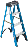
Drawing a boe-bot, you can use the actual unit to measure off of, but if you can access on-line information that gives you the exact dimensions, this can help you create a more accurate and quicker result in your reproduction and digitization of the boe-bot. When first getting the boe-bot kit, you would have to follow instructions on putting it together from the ![]() boe-bot manual, which would also show you what parts go where.
boe-bot manual, which would also show you what parts go where.
Some component information can be found on the Parallax web site which they sell the usb boe-bot for example:
- Brushed-aluminum chassis with mounting holes
 drawing link
 - Parallax Continuous Rotation Servo Dimensions: 2.2 x 0.8 x 1.6 in (55.8x 19 x 406 mm) excluding servo horn drawing link
- Dimensions for the Boe-Bot Robot drive wheels dimensions link and 1" Tail wheel ball
- Board of Education development board with a BASIC Stamp 2 micro-controller manual link
- Battery holder
 close-up image with case dimensions: 3.12 x 2.31 x 0.67 in (8 x 5.7 x 1.7 cm)
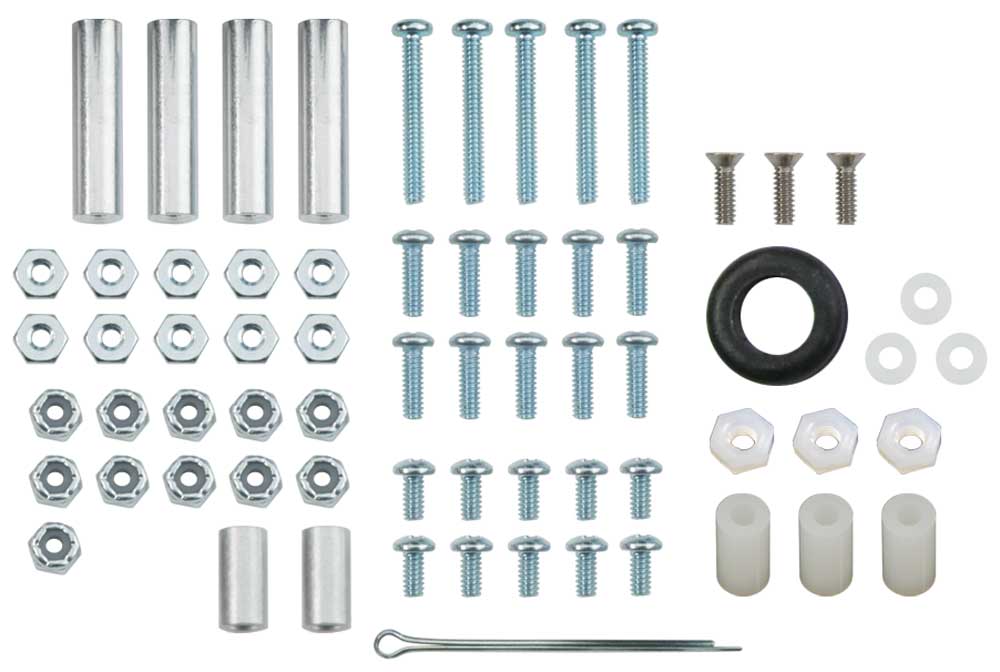
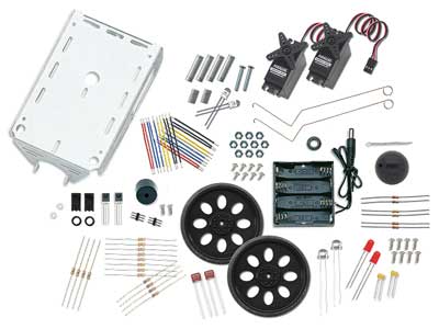
The following list shows the ![]() hardware fasteners used to support and fasten all of the boe-bot components:
hardware fasteners used to support and fasten all of the boe-bot components:
- 1/16" cotter pin
- 3/8" #4-40 pan-head screw
- 3/16" #4-40 flat-head screw
- 7/8" #4-40 pan-head screw
- 1/4" #4-40 pan-head screw
- 1" round #4-40 aluminum standoff
- 1/2" #4 aluminum spacer
- Rubber grommet
- #4 nylon washer
- #4-40 nylon core locknut
- #4-40 nut
- #4-40 Nylon nut
- #4 Nylon spacer, 1/2"
Remember you may find fasteners in the SolidWorks toolkit, otherwise you will want ot use McMaster-Carr to download specific fasteners to use with your model. Although a lot of the parts on the boe-bot are custom and theirfore not readily avliable, you may find the odd component from online CAD part suppliers that you could download, to use with your model.
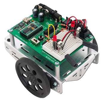 Boe-Bot
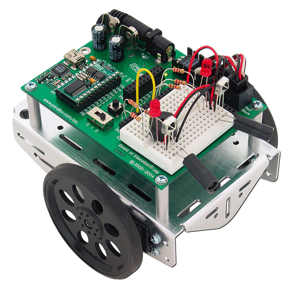
Using the actual parts create a digital 3D CAD model of the boe-bot with appropriate colours/textures using the following general steps:
- Start with the sheet metal frame then locate all mounting holes - step resource doc
- Create the servo and create the assembly by bringing in the frame then the servos, use toolbox for mounting screws
- Create the two front flat wheels and a back sphere wheel, then bring into the assembly and use toolbox for mounting screws, the cotter pin you may download
- Create the circuit board as a separate part,
- Create the round stand-off mounts with thread
- Make the electronic components such as the as the bread board, BIOS chip, power switch, reset button, power pins, servo jacks, capacitors, etc all as individual parts, create a sub-assembly with circuit board and parts made here
- Create an assembly drawing, and for each of the major components made such as the frame, circuit board, wheel, and servo motor (5 drawing files)
- Hand in folder holding all assemblies, part model files, and jpg's
- If time permits, battery pack found underneath the chassis, finer electronic components, and electronic board decals
There are many small features that can be drawn in, but suggest for the electronic components, to draw the basic geometric shapes first, then if you have time, you can go back and improve the detail. For example the bread board has a pattern of pin contact openings that can be made using the pattern tool, again, stressing - if you have time.

For advanced additional challenge, design and draw a support function for your boe-bot. Ideas can be reviewed on the parallax boe-bot accessories, to see what other possibilities there are. This will require some additional research and time to complete.